0
\$\begingroup\$

Excuse me for this simple question.

Current Source/Sink

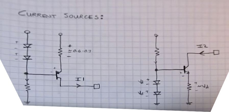
Can someone tell me how this circuit works?

In the video, it is said that, the voltage drop across the resistor connected to NPN/PNP will be only a diode drop. But I'm not grasping that. Can someone simplify it better?

\$\endgroup\$
8
  • 1
    \$\begingroup\$ Do you know the voltage across component connected in parallel must be the same? \$\endgroup\$
    – G36
    Commented Aug 4, 2019 at 10:51
  • 2
    \$\begingroup\$ why did you choose to photograph this at an angle? \$\endgroup\$ Commented Aug 4, 2019 at 11:06
  • 3
    \$\begingroup\$ I tried my best, but there's only so much finite effort and image processing can do to correct a slanted image and heavy lense distortion and finite depth of field. \$\endgroup\$ Commented Aug 4, 2019 at 11:11
  • 2
    \$\begingroup\$ also, "can someone tell me how this circuit works", and then showing two circuits isn't great. \$\endgroup\$ Commented Aug 4, 2019 at 11:18
  • 2
    \$\begingroup\$ @Newbie: What level of electronics understanding do you have? Do you understand the forward voltage drop of a diode? Do you understand the base emitter drop of a forward biased transistor? If you let us know you will get an answer pitched at your level. \$\endgroup\$
    – Transistor
    Commented Aug 4, 2019 at 11:47

1 Answer 1

1
\$\begingroup\$

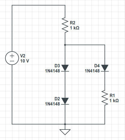
A first approximation for the NPN circuit would be:
enter image description here

Where D4 represents the Base-Emitter junction. It is clear that the added voltages across D2 and D3 equals the voltage across D4 added to the one across R1. Since the voltages across diodes directly polarized don't vary too much with the current, it is also clear that the voltage across R1 is similar to a voltage drop across a diode.

\$V_{D2}+V_{D3} = V_{D4} + V_{R1}\$

\$ V_{D2} \approx V_{D3} \approx V_{D4} \$

Analyzing the circuit with the transistor, if it is kept far from the saturation, the base current will be a small fraction of the emitter current. If \$V_{R1}\$ doesn't change considerably, also its current will remain practically constant. Since \$ I_C \approx I_E \$, the circuit will keep the current entering the collector almost constant. To do that the \$V_{CE}\$ will change, so if the transistor goes into saturation, the current control will not be effective.

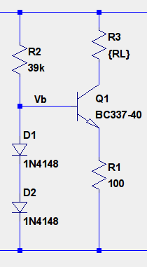
Maybe it easier to understand if you connect a load resistor (\$R_L\$) between the collector and the voltage supply. You can vary \$R_L\$ from 0 to a value which allows the \$V_{CE}\$ voltage to stay above the saturation voltage.
enter image description here

Just flip everything upside down for the PNP circuit.

\$\endgroup\$
3
  • \$\begingroup\$ Thank you for the detailed answer. But could you just help me with my two questions. While the PNP circuit is acting as the current source, at what region will the transistor operate and why? \$\endgroup\$
    – user220456
    Commented Aug 4, 2019 at 14:40
  • \$\begingroup\$ The NPN and PNP circuits operate exactly in the same way. Only the polarization is different (voltages are inverted). Both transistors are in the active region because the BE is directly polarized and Vce is large enough so they don't go into saturation. If this happens, the circuit will not be able to function as a current source. I think it is better if you try to understand a complete circuit, like the ones I put in the answer, instead of the ones you mention, just with an arrow representing the current. \$\endgroup\$
    – devnull
    Commented Aug 4, 2019 at 23:13
  • \$\begingroup\$ It would also be easier if you understand well the NPN circuit, for example, since it is clearer to see that as RL grows, the collector voltage will get lower. Once the collector voltage get below the base voltage the CE junction will start to get directly polarized and the transistor will approach saturation. Once you get that, just flip the voltages for the PNP circuit. \$\endgroup\$
    – devnull
    Commented Aug 4, 2019 at 23:17

Your Answer

By clicking “Post Your Answer”, you agree to our terms of service and acknowledge you have read our privacy policy.