3
\$\begingroup\$

enter image description here

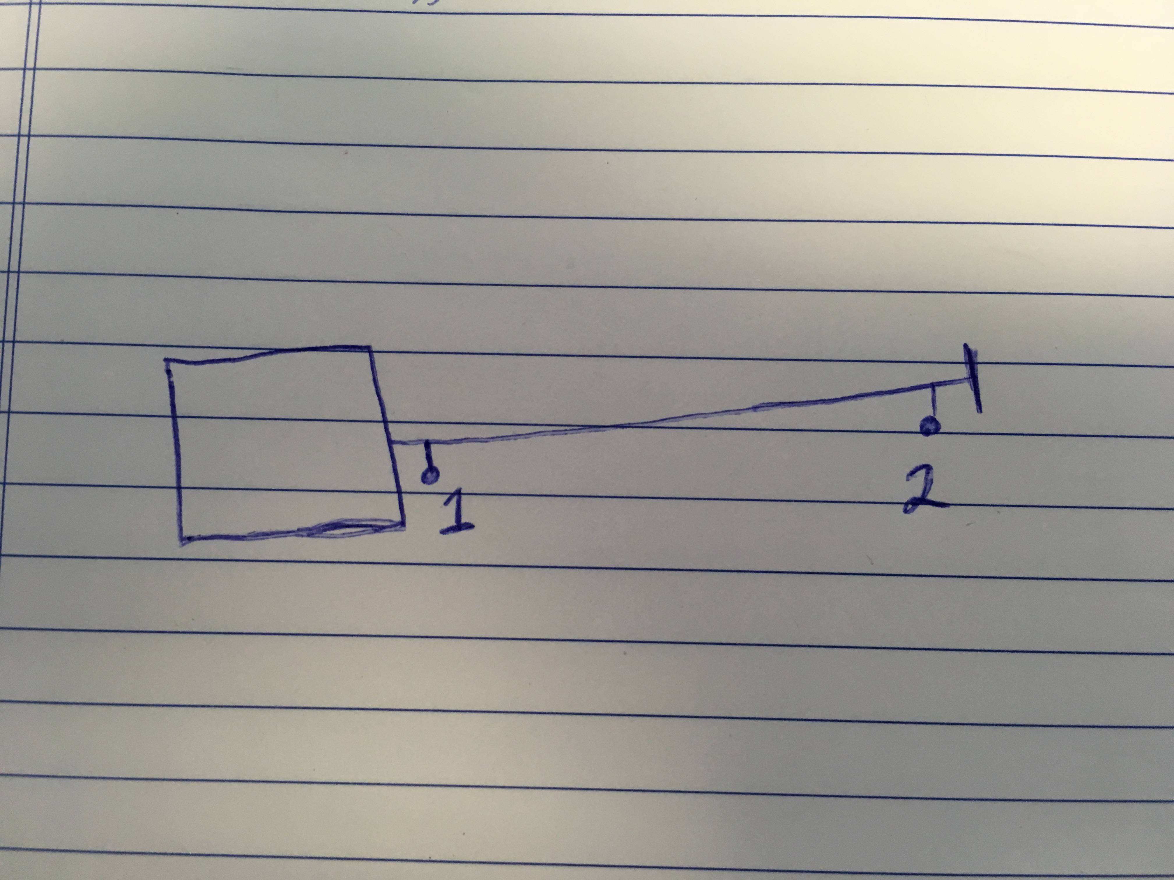
Let's say you have a wire connected to a device that you can switch between high-voltage and ground voltage. The wire is not connected to anything on the other end. You're observing the voltage in two places: one (#1 in the pic) very close to the device and one (#2 in the pic) at the far end of the wire. The wire has some load capacitance, so between the time the voltage toggles from low to high or high to low and the time that the wire is uniformly "pressurized", #1 and #2 will have different readings since the signal does not propagate instantaneously.

My question is this: would the voltage change propagate down the wire as a "sharp line", where at some point in time #1 would be close to high and #2 would be close to low? Or would #1 and #2 rise/fall more or less in tandem with just a tiny delay between the two?

I have a (relatively) long wire in a digital circuit where #1 and #2 are gate inputs that I want to act on with a picosecond-scale time gap between them; would #1's signal be stable before #2's was stable in the event of a change of voltage on the wire? Like, is this feasible or am I barking up a silly tree?

I've confirmed that I can delay a signal by a few picoseconds by lengthening a wire from point A to point B (not surprising). But I want to know if I can get (and stay stable enough once I initially get there) from point A to point B_1 in time_x and point B_2 in time_x + time_y just by spacing them out on the same wire.

\$\endgroup\$
9
  • 4
    \$\begingroup\$ Have you looked into transmission line theory or reflections? There is an answer somewhere on this website to a link with animated graphs. I think the topic was reflections. \$\endgroup\$
    – DKNguyen
    Commented Aug 7, 2019 at 19:18
  • \$\begingroup\$ I haven't yet. Didn't even know what to look up. I'm a digital guy getting my feet wet in the analog world. Thanks; I'll check out transmission line theory & reflections and hopefully find that animation you're referring to. \$\endgroup\$ Commented Aug 7, 2019 at 19:28
  • 2
    \$\begingroup\$ You have important and valid questions. This is the realm of signal integrity, which is based on transmission line theory. I strongly recommend you spend some time learning the basics of it. One important element missing in your drawing is the ground return, which is critical to determine how the signals will behave. \$\endgroup\$
    – joribama
    Commented Aug 7, 2019 at 19:45
  • 1
    \$\begingroup\$ This looks like a cross-post of this question on Physics.SE. \$\endgroup\$
    – The Photon
    Commented Aug 7, 2019 at 19:51
  • 1
    \$\begingroup\$ I found the link with the transmission line animation. I had it bookmarked but forgot about it: helloworld922.blogspot.com/2013/04/… \$\endgroup\$
    – DKNguyen
    Commented Aug 31, 2019 at 18:49

3 Answers 3

5
\$\begingroup\$

My understanding is that you want to feed a logic signal to two separate logic circuits with a delay in the order of pico-seconds.

Your proposal of using a single wire with two different taps makes sense. The #2 point will receive the signal with a certain delay like you expect. The problem is that the signal will reflect at the end of the wire and come back to node #2 and #1. Depending on the termination on the driver it will also reflect on the left side and come back to #1 and #2. The reflections will continue multiple times. What you'll actually see on #1 and #2 will be the superposition of all these reflections, which most certainly is not what you expect to have.

In order for your 1-wire approach to work, you need a few modifications. First, instead of a single wire, you need an extra wire for the ground return. I recommend you use a twisted pair. Then you need to add a resistor at the end of the wire to work as a termination load. Its value needs to be the same as the characteristic impedance of the transmission line implemented as a twisted pair. This will prevent reflections on the end of the wire pair. You don't have to worry about reflections on the driver side if you don't have reflections on the load side. Depending on the output resistance of your driver, the signal you will get on #1 and #2 may have lower amplitude than what you need (think about a voltage divider between the output impedance of the driver and the characteristic impedance of the transmission line). To mitigate this you may use several drivers in parallel to lower the source impedance or use different supply voltages.

Another option is to have two identical drivers with the same input, the first connected to a wire leading to #1 and the second longer wire leading to #2. The difference in length between the wires will determine the delay you are looking for. You also need a separate ground return for each connection like the single-wire solution. In this case, you will also have reflections at the end of the wire, since logic gate inputs are typically high impedance. However this reflection will not distort the signal because you are tapping right at the reflection point. Reflections on the driver side will cause you trouble, so you'll have to have matching on that side instead. The idea is to add a series resistor close to the driver so that this external resistance added to the source impedance of the driver equals the characteristic impedance of the twisted pair. One advantage of this approach is that you don't suffer from amplitude attenuation at nodes #1 and #2 (the traveling signal amplitude is half the supply voltage due to the source matching, but doubles in amplitude when reaches the end due to the high impedance reflection).

\$\endgroup\$
1
\$\begingroup\$

The circuit would look like this:

schematic

simulate this circuit – Schematic created using CircuitLab

The circuit would complete through the air, air has resistance which varys according to composition and humidity. The inductance of the wire would be the limiter for the voltage in the wire (and could be imagined as many small resistors and inductors in series).

\$\endgroup\$
3
  • \$\begingroup\$ In the end, this wire will be buried in a packaged chip somewhere. Makes me doubt the air resistance applies. Am I wrong to think that? \$\endgroup\$ Commented Aug 7, 2019 at 19:45
  • 1
    \$\begingroup\$ @PistoletPierre Well, then you'd have the resistance of the plastic that surrounds it instead. \$\endgroup\$
    – Hearth
    Commented Aug 7, 2019 at 19:49
  • \$\begingroup\$ Which would be much lower than that of air \$\endgroup\$
    – Voltage Spike
    Commented Aug 7, 2019 at 19:55
0
\$\begingroup\$

tl; dr version: The voltage step propagates as a wave along the wire.

Yes, your scheme will work if you take care of termination on the line so you don't get unwanted reflections.

The speed of the voltage-step wave propagation is some fraction of the speed of light, C. For a low-loss coax cable, the speed will be about 0.8 C. For a microstrip PCB trace it's more like 0.5 ~ 0.6 C (about 140-170ps/inch.)

You can take advantage of this fact to create a delay line, assuming you take care of signal integrity issues to ensure the waveforms you pick off are clean.

Here's a video with a visualization of wave propagation on a wire, unterminated and terminated: https://www.youtube.com/watch?v=ozeYaikI11g

In this video, the wire (or, more correctly, transmission line) is modeled as a distributed inductance and capacitance. With an unterminated transmission line, the wave bounces back toward the source with the same polarity (adds to the waveform as a positive step.) If it's terminated at the far end, the wave is absorbed at the end. If the line is shorted, the reflected wave is opposite polarity.

\$\endgroup\$
3
  • 3
    \$\begingroup\$ Or if you like me can't stand the baby-voice-on-shopping-mall-muzak style, a video for real engineers by real engineers: youtu.be/I9m2w4DgeVk?t=337 \$\endgroup\$
    – pipe
    Commented Aug 7, 2019 at 21:18
  • \$\begingroup\$ Complete with pocket protector.... awesome! \$\endgroup\$ Commented Aug 7, 2019 at 21:34
  • \$\begingroup\$ @pipe - what a cool vintage video! :) \$\endgroup\$
    – joribama
    Commented Aug 8, 2019 at 2:09

Your Answer

By clicking “Post Your Answer”, you agree to our terms of service and acknowledge you have read our privacy policy.

Not the answer you're looking for? Browse other questions tagged or ask your own question.