1
\$\begingroup\$

This is a continuation from this question (sort of)

I want to replace the relays from an existing circuit with optocouplers and had trouble how to read the optocoupler datasheets as well as understanding how they operate. I think I understand a little now, but still consider myself quite newbish in the topic.

I changed the optocoupler from the previous question, since I've found that it's probably easier to start with a more widespread component (4N25 or 4N27).

If I understand opto-couplers a bit better I might switch to a more fitting opto-coupler for my appliance.

So, to start, here is the schematic with relays:
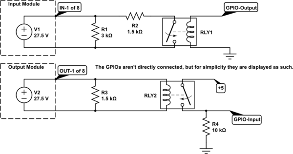
schematic

simulate this circuit – Schematic created using CircuitLab

Since optocouplers consist of LEDs an input protection resistor is necessary. Also there's a voltage drop from the transistor on the output.

For the Input Module the schematic is almost identical, since the voltage drop of the transistor is neglect-able on the module side. But for the Output Module I have trouble finding the right resistor so that the Passive (\$ I_{passive} = 10mA \$) / Active state (\$ I_{active} = 20-30mA \$) for the monitored output are still correct.

The output module has an internal resistor of 26K7 ohm and a MOSFET bypassing that resistor when active.

Here are my schematics with optocouplers:
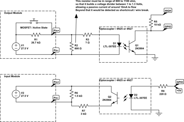
schematic

simulate this circuit

I also don't really know how to calculate the resistor for the LED.

It seems to me like the output module can't be used with optocouplers, as the passive state is enough to activate the led / saturate the transistor.

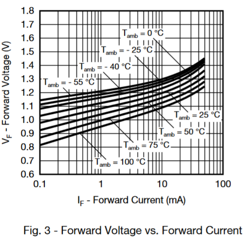
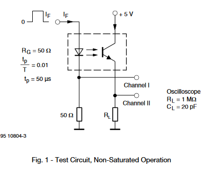
Reading the datasheet, there's this figure, which tells me the 4N25 would become active from the passive state of the output module.

EDIT:

R2 on the output module is mandatory because it's a monitored output.

When the output is inactive, the internal 26K7 ohm resistors will limit the current to around 10mA (in series with 800 ohm). This 10mA basically tells the circuit that there's no wire-break.

Now, when the output is active, the internal resistor gets bypassed. With the bypass all I have is the 800 ohms, which needs a parallel resistor to limit the current on the LED.

But that's where I fail, since I don't know how to size R3 properly.

enter image description here

I feel like I'm getting this wrong.
\$\endgroup\$

2 Answers 2

1
\$\begingroup\$

A few comments about your assumptions and notes: 1) Your note states that 10mA must flow for broken wire detection. But using ohm's law and the voltage and resistance values you provided: $$I=\frac{V}{R} \rightarrow \frac{27.5V}{26.7kΩ}=.001A\rightarrow 1mA$$ Knowing this much lower "passive" value, make this a bit easier to design with. So now what you need to do is differentiate between 1mA and 20mA. Your method is one way to do this, and you can complete it with a zener diode:

schematic

simulate this circuit – Schematic created using CircuitLab

R3 is then calculated as follows: $$\frac{(27.5V-10V-1.3V)}{20mA}=810Ω$$

So in summary, R2 will provide a path for the 1mA sense current while D2 blocks the opto from turning on. When the mosfet activates and presents the full 27V to the output, then the zener will break over and conduct while R3 limits the current to 20mA through the opto's LED.

\$\endgroup\$
4
  • \$\begingroup\$ Oh boy... I shouldn't look at circuits all day. You're right, it's 1mA.. I mixed it up with the 10mA required for the passive state of the input module. Geez. \$\endgroup\$
    – HackXIt
    Commented Aug 12, 2019 at 20:28
  • \$\begingroup\$ Zener diodes. The answer I've been secretly looking for. \$\endgroup\$
    – HackXIt
    Commented Aug 12, 2019 at 20:36
  • \$\begingroup\$ Why do you use the 1N4740A in your example and not 1N4749A, which has a nominal voltage of 24V? The resistor would be \$ \frac{27.5V-24V-1.3V}{20mA}=120Ω \$ ... Also in your calculation you used 26.7V, which should be 27.5V instead. \$\endgroup\$
    – HackXIt
    Commented Aug 12, 2019 at 21:17
  • \$\begingroup\$ @HackXIt Good eye, I did the math correctly, but typed it in wrong. So the resistor value stays the same. You could use that value of zener if you want, just make sure you get the power ratings correct. 24V*10mA≈0.5W! A larger voltage zener will dissipate more of the power. The 10V zener will split the power more evenly between R3 and D2. \$\endgroup\$
    – Aaron
    Commented Aug 13, 2019 at 1:11
0
\$\begingroup\$

R3 needs to be sized to turn the LED on when you apply voltage, but not burn it out (it is an LED)

With LED's (or any diode) its easiest to limit the current with a resistor like this:

enter image description here Source: 4N25-X datasheet

The max current the diode can take is 60mA with a recommended value of 50mA. Since the voltage is 27.5V and the diode is a 1.3V drop, the resistor would need to drop 26.2V. So we use V/I=R, 26.2V/0.05A = 524Ω minimum for the resistor. (you don't need the 800Ω resistor to create a voltage drop, it will only burn up heat). Going with a lower current than 50mA for the LED current is probably a good idea (26.2V/0.03A = 870Ω)

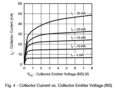
This graph shows the relation for different forward currents of the LED of the transistor side of the device (the brighter the LED, the more forward current the transistor will get).

enter image description here Source: 4N25-X datasheet

\$\endgroup\$
7
  • \$\begingroup\$ I need the 800 Ohm for the 10mA on Pin(-) of the Output Module. The problem is that when the Output is activated, the 26K7 resistor that is in the output module internally gets bypassed, and so if I don't put a resistor before the LED it will burn through. But I also can't get rid of the 800 ohms, because then I would lose the 10mA of the inactive state, which are mandatory.. Sorry, I need to rephrase my question \$\endgroup\$
    – HackXIt
    Commented Aug 12, 2019 at 19:37
  • \$\begingroup\$ @HackXIt These devices are best used to switch things on and off, they are highly depended on temperature, if you try and maintain a current, it will vary with temperature. Maintaining a current is not a good idea. The LED should be on or off. \$\endgroup\$
    – Voltage Spike
    Commented Aug 12, 2019 at 19:40
  • \$\begingroup\$ Maybe what I'm trying to do is not even possible. Like, I can't use a monitored output to drive an optocoupler, because the "monitoring" will damage the LED over time? \$\endgroup\$
    – HackXIt
    Commented Aug 12, 2019 at 20:14
  • \$\begingroup\$ No, it won't. But you may not get the results you want. What are you doing with the GPIO on the otherside of the opto? Are you detecting high/low or do you plan on connecting it to an ADC? \$\endgroup\$
    – Voltage Spike
    Commented Aug 12, 2019 at 20:24
  • \$\begingroup\$ Simply detecting High and Low. \$\endgroup\$
    – HackXIt
    Commented Aug 12, 2019 at 20:34

Your Answer

By clicking “Post Your Answer”, you agree to our terms of service and acknowledge you have read our privacy policy.

Not the answer you're looking for? Browse other questions tagged or ask your own question.