13
\$\begingroup\$

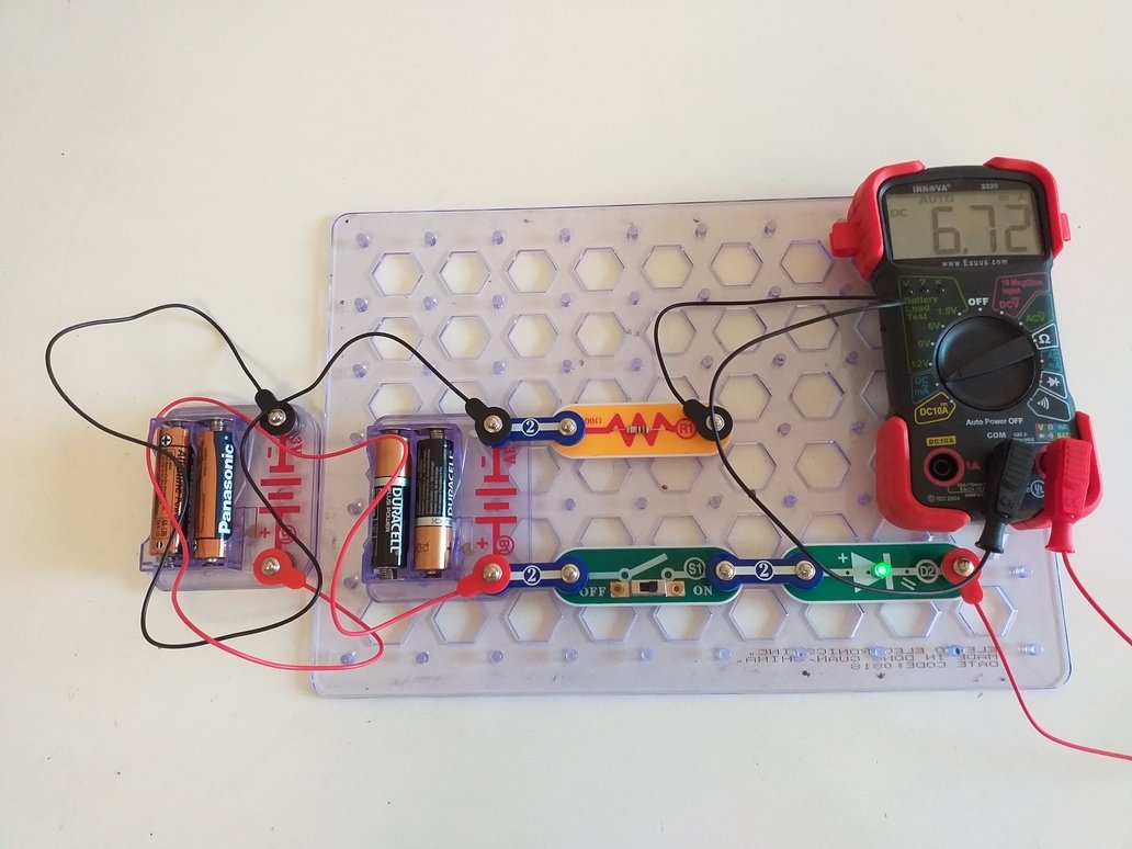
I built a simple circuit consisting of two battery holders each including x2 1.5 V batteries, a slide switch, a LED and a 100 ohm resistor. The current I measured with a multimeter when the two battery holders were connected in series (and the switch ON) was 25.9 mA:

Enter image description here

I then connected the battery holders in parallel by connecting the positive contacts of the battery holders with the red jumper cable and the negative contacts of the battery holders with the black jumper cable:

Enter image description here

This time the measured current is 6.72 mA. Shouldn't it be greater than when the battery holders are connected in parallel?

\$\endgroup\$
6
  • 13
    \$\begingroup\$ It's really great you are performing such experiments and asking questions! The answer is that with the battery systems in series, the total voltage is larger: \$6\:\text{V}\$. When in parallel, the voltage is about \$3\:\text{V}\$. (It's not exactly a good idea to put them in parallel, but I'm skipping that concern right now because it's not important at the moment.) The parallel arrangement can in theory supply more current. But that's only if the circuit asks for more. In your case, the larger series voltage causes your circuit to request more current because the voltage is larger. \$\endgroup\$
    – jonk
    Commented Aug 18, 2019 at 7:14
  • 2
    \$\begingroup\$ Just a wow to see the efforts from you and the nice board too. What is it called? \$\endgroup\$
    – User323693
    Commented Aug 18, 2019 at 7:56
  • \$\begingroup\$ @Umar They are Snap Circuits stuff. See here. \$\endgroup\$
    – jonk
    Commented Aug 18, 2019 at 8:09
  • \$\begingroup\$ @jonk I am gonna buy many of those and distribute soon \$\endgroup\$
    – User323693
    Commented Aug 18, 2019 at 8:15
  • \$\begingroup\$ @Umar I've bought some too. I've also contacted them in order to buy empty modules I can fill, myself. They are a nice concept. \$\endgroup\$
    – jonk
    Commented Aug 18, 2019 at 8:27

8 Answers 8

14
\$\begingroup\$

First off, I want to warn you just a little bit about putting battery systems in parallel. It's usually not a good idea because often the two batteries (or battery systems) don't have exactly the same voltage. If they are different, then the one with the larger voltage will supply some current into the battery with the lower voltage and this often isn't a good thing. It also messes up your experiment, somewhat, because it adds another complication to it.

In this case, you are curious and imagine that two batteries in parallel can supply more current. So it doesn't serve your purposes to use only one in your experiment because it doesn't test your assumptions. So you have to do it the way you did. But I just want you to also realize that there is another unknown (to you) factor that you aren't accounting for in your experimental design. But it's not enough to worry about, for now.

So set that aside...

Let me suggest a new idea for you to consider. Suppose that the green LED you have requires exactly \$1.9\:\text{V}\$ in order to "turn on" and that it also has, unknown to you, an internal resistor of exactly \$50\:\Omega\$. You can't get inside the LED to see these things. But let's say, as a thought experiment, that this is the way this particular LED works.

Also, let's assume that your battery systems provide exactly \$2.9\:\text{V}\$ each. If you put them in series then you are applying \$5.8\:\text{V}\$ to the circuit. If you put them in parallel then you are applying \$2.9\:\text{V}\$ to the circuit. The only difference here may be the current compliance (the ability to supply more or less current to a load, if required.)

Your assumption is that if the current compliance is more, then the current is more. But that may be true sometimes and not others. So, for now, let's use my above idea about the LED and see where that takes us.

Your series circuit includes also a \$100\:\Omega\$ resistor. Taken together with my hypothetical internal \$50\:\Omega\$ resistor inside the LED, there is a total series resistance in the circuit of \$150\:\Omega\$ (let's just assume I'm right for now.) Plus, the LED itself (the one inside the package that you cannot actually touch) also requires (subtracts) \$1.9\:\text{V}\$ from the applied voltage before we can compute the current. (You can see that the LED is ON in both cases, so this must be true if my assertion is correct.)

So in the batteries-in-parallel case you have \$I_\text{parallel}=\frac{2.9\:\text{V}-1.9\:\text{V}}{150\:\Omega}\approx 6.7\:\text{mA}\$ and in the batteries-in-series case you have \$I_\text{series}=\frac{2\cdot 2.9\:\text{V}-1.9\:\text{V}}{150\:\Omega}\approx 26\:\text{mA}\$.

This would appear to predict your measurements within a reasonably small error.

So which idea do you think works better here? Your thoughts about two parallel battery systems doubling the current? Or my suggestion about how an LED may behave? Do you have still further ideas that you may want to consider? How might you test or validate my above suggestion? Can you think of another way to change your circuit that might put my suggestion to another test to see if it still holds up? Or can you think of another voltage measurement or current measurement you might try to test it?

\$\endgroup\$
6
  • 4
    \$\begingroup\$ I appreciate your time and effort you put in helping us overall. +1 for your ability to explain anything to anyone \$\endgroup\$
    – User323693
    Commented Aug 18, 2019 at 8:01
  • \$\begingroup\$ @jonk Why isn't the voltage drop of the resistor also substracted from the applied voltage, together with the 1.9V of the LED itself, in your calculation above? \$\endgroup\$
    – korppu73
    Commented Aug 19, 2019 at 7:46
  • \$\begingroup\$ @korppu73 The LED voltage is first subtracted from the supply voltage. Then the remainder voltage is, in fact, applied to the series resistance that remains. But I've suggested to you the idea that there is an internal resistance within the LED to be added. The external resistor you included does subtract its own portion. But we don't know how much without also taking into account the internal LED resistance. \$\endgroup\$
    – jonk
    Commented Aug 19, 2019 at 20:09
  • \$\begingroup\$ @jonk I measured the voltage drop of the led, by connecting the probes of the multimeter at each end of the led, and the value is 3.30v Given that the measured current of the circuit is 26mA, would the internal resistance of the led, then be, from Ohm's law: 3.3/0.026 = 126.92 Is this correct? \$\endgroup\$
    – korppu73
    Commented Aug 20, 2019 at 6:37
  • \$\begingroup\$ @korppu73 No. But that's a very good idea, measuring the voltage across the LED. Typically, an LED is most simply (and still usefully) modeled as a voltage source plus a resistor. This means you need to work out TWO VALUES, not one. You need to work out the voltage and also the resistance. For that, you need two equations. And to get two equations you need TWO TEST CASES, at at least. You have one such measurement. Now make another where the current is significantly different. Then measure the voltage across the LED, again. Now with two measurements we can work out the two values. \$\endgroup\$
    – jonk
    Commented Aug 20, 2019 at 7:34
7
\$\begingroup\$

In the initial case you have 6V applied across your LED circuit. In the latter case it is Only 3V.

Ohm's law states that the current through a conductor between two points is directly proportional to the voltage across the two points.

When the batteries are arranged in series, the voltage adds up. Higher the voltage, higher will be the current drawn by your circuit.

When the batteries are connected in parallel, the voltage will remain the same. (The current supplying ability will increase, but let us keep it aside).

There are some tiny deviations that occur but I believe that you will learn a bit later.

Please post your doubts in the same question or in the comments and I will be happy to answer as much as I can.enter image description here

\$\endgroup\$
1
  • \$\begingroup\$ But actual batteries don't have the exact same voltage. There is a variation. If there wasn't any internal resistance the current would be infinite (for ideal voltage sources). What about the magic smoke? \$\endgroup\$ Commented Aug 18, 2019 at 16:33
5
\$\begingroup\$

What you have discovered is Kirchhoff's voltage and current laws and Ohm's law.

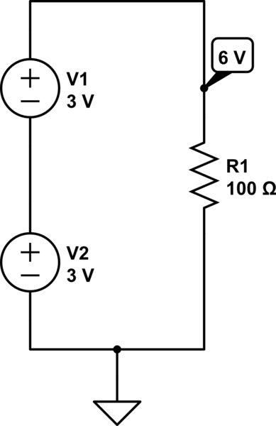
Put simply, applying Kirchhoff's current law gives that when voltage sources such as batteries are connected in series their voltages add up.

Let’s forget about the LED for a moment; we will come back to it.

In the diagram below, the load (the 100 ohm resistor) sees 6 V across it.

schematic

simulate this circuit – Schematic created using CircuitLab

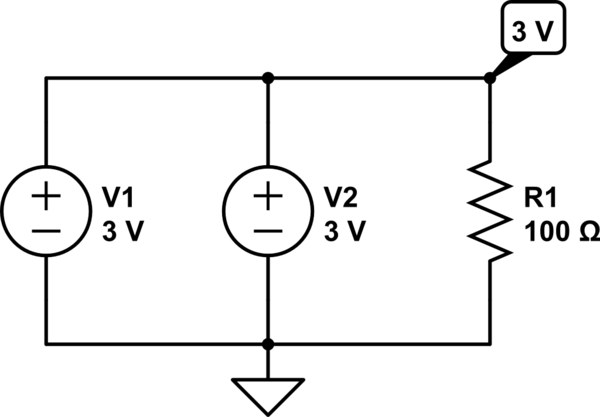
In this circuit (below), Kirchhoff's voltage law will tell you that the voltages do not add up, because the voltage sources are in parallel. However, the current drawn by the 100 ohm load is split between the two.

schematic

simulate this circuit

Now let's not forget about the LED;

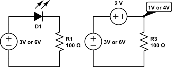
An LED (light-emitting diode) is, as the name suggests, a "diode". These devices are complicated to describe to satisfaction in a short answer like this one, but for the purpose of this explanation just think of it as having a constant voltage across it, regardless of what the current through it is. With that simplification the voltage across the diode can simply be subtracted from the voltage caused by the voltage sources (batteries) which are either in series (6 V) or in parallel (3 V). The voltage across an LED depends on what LED it is, but it is typically between 1.8 V and 2.1 V depending on the colour.

The circuit below shows the effect of the LED:

schematic

simulate this circuit

Now to Ohm's law;

V = R*I

I = V/R

R = V/I

where

V = Voltage

I = Current

R = Resistance

Applying Ohm's law;

4 V / 100 ohm = 40 mA

1 V / 100 ohm = 10 mA

I have just used typical values for this example, but you can use Ohm's law to go backwards and calculate what the voltage across the LED is, or you can measure it and calculate other values. Have fun!

By the way, it is great that you are doing your own experimentation like this, but next time don't connect batteries in parallel like that. They don't like it ;) (I am not going into the details now.)

\$\endgroup\$
2
\$\begingroup\$

I try to explain electricity by comparing it to a fluid. Voltage, or pressure, is the cause of current or flow, which is the effect. Generally increasing pressure will increase flow. When you connect batteries in series you are increasing the voltage or pressure, so for a simple resistive circuit, which yours is similar to, you will produce more current or flow. When batteries are connected in parallel, you are not increasing the pressure, but you are giving the batteries the possibility to supply more current if the circuit conditions allow it.

\$\endgroup\$
1
  • 2
    \$\begingroup\$ You can also explain it as table legs. When you add more legs to a table, it CAN hold up more weight but only if you put more weight on to it. If you don't put more weight onto the table at best, it makes the table sag less which is similar to reducing voltage droop. \$\endgroup\$
    – DKNguyen
    Commented Aug 18, 2019 at 8:32
1
\$\begingroup\$

The real workhorse behind the current is voltage. More the voltage for a fixed resistance, more will be the current. In your first case the series equivalent voltage is 3+3=6V.

In second case, because the batteries are in parallel and of equal value, their equivalent voltage remains the same i.e 3V

Hence more the voltage, more the current.

But wait,then why we read in our textbooks that Parallel arrangement helps to increase current? Well, that doesn't really increase the current but increases the upper limit of current which our batteries are able to provide. That means the current providing capacity of the system increases. Current would still depend on the voltage. But if the voltage goes higher and higher, the series system may not be able to provide that much current as predicted by ohms law. But the parallel system may provide it . Though it will fail too, but at even higher voltages.

\$\endgroup\$
1
\$\begingroup\$

Everything has some resistance.

AA Battery ~1 Ohm ~1.5 to 1.6 V source.
White LED ~ 15 Ohms @~3.1 V @20 mA, 2.8 V off.
100 ohm resistor.
Wire ~ x mOhm

Thus parallel bank = 3.1 V (new) - 2,8 V LED = (est.) 300 mV divided by the loop resistance = 116 ohm would be < 3 mA close to your result.

Then when 2 banks in series 6.2V(Vbat)-2.8V (Wh. LED threshold) = 3.4V / 116 Ohms (loop resistance) = 29 mA which is also close to your reading due to tolerance on estimates.

\$\endgroup\$
0
\$\begingroup\$

Not quite so simple. When you put two cells in parallel, in effect you put the internal resistances of the two cells in parallel, thus lowering the total resistance in the circuit. Even if the cells have different terminal, open circuit Voltages, and different internal resistances, you are reducing the overall resistance of the whole circuit. And so, more current should flow. If you don't see a higher current flow, then your measuring system is not sufficiently sensitive. For the short time of your experiment, we can ignore the temperature coefficient of resistance of all components in your circuit.

\$\endgroup\$
-1
\$\begingroup\$

Caution: remove the batteries from your test setup when it is not in use. Two of the batteries shown in your test setup are likely to leak corrosive chemicals into the battery holder if allowed to discharge completely and remain for a long time.

You claim that the current does not increase with the parallel battery. How certain are you of this? What if the current increase is very slight, and is less than the ability of your meter to measure?

Here is your assignment:

-- get a more accurate meter, the best you can borrow

-- measure the current with battery #1 alone.

-- measure the current with battery #2 alone.

-- measure the current with both batteries in parallel.

I predict that the third measurement will be greater than the minimum of the first two.

It is common in indroductory electronics to consider batteries as a source of voltage. But batteries are really very complex devices for which the voltage source is only an approximation. A better approximation is a voltage source with a low-value resistor in series. You can actually estimate the value of this series resistor by measuring the voltage drop when a load is applied to a battery and using the usual rules for series resistors and ohm's law. Most electrical engineering stops with this, but there are even more complex models for a battery that represent its behavior even more precisely.

Learn all you can, but always be skeptical and ask challenging questions while I recharge my cell phone.

\$\endgroup\$
1
  • \$\begingroup\$ One would not expect the current to change -- unless the load were challenging how much current the battery could provide, or the batteries were near drained. The experiment is fine, the equipment is fine. The point about internal resistance is fine, but unlikely to have any real impact in this scenario. \$\endgroup\$ Commented Aug 30, 2019 at 15:54

Your Answer

By clicking “Post Your Answer”, you agree to our terms of service and acknowledge you have read our privacy policy.

Not the answer you're looking for? Browse other questions tagged or ask your own question.