1
\$\begingroup\$

I have two multimeters - granted, they're both the super cheap DT830B types, but slightly different models and one is straight from the packaging.

I also have two bags of LEDs - bright red and bright blue (from Aliexpress). They did not have a great indication of forward voltage, saying something like "1.8V - 3.4V" for both, clearly unhelpful (3.3V "popped" the first one I tried: I'm guessing that range is for across their range of LED colours).

With either meter and either LED, in diode test mode, all I get is a solid "1" displayed. In all cases, the LED lights dimly, but no reading. On the newer one, the display briefly displays a number (~1000-~1700) before returning to, "1".

I'm pretty baffled. These are standard 5mm LEDs as best I can tell, other than being called "ultra bright". Since the documentation around them is flaky, I really wanted to set the voltage/current correctly, rather than assuming 20mA, for instance.

What's going on here - crap/broken multimeters? Crap/broken LEDs? Misunderstanding? Thanks!

\$\endgroup\$
4
  • \$\begingroup\$ The forward voltage isn’t really all that important. What is important is the forward current, you must keep the current less than the maximum, which is usually around 20mA. When you put 3.3V across the LED you will have exceeded 20mA. \$\endgroup\$
    – HandyHowie
    Commented Aug 18, 2019 at 10:12
  • \$\begingroup\$ @HandyHowie thanks, I'm wondering how can I determine the maximum w/o a datasheet? \$\endgroup\$ Commented Aug 18, 2019 at 10:34
  • \$\begingroup\$ You can’t work it out, you need the datasheet. \$\endgroup\$
    – HandyHowie
    Commented Aug 18, 2019 at 10:46
  • \$\begingroup\$ Check your multimeters manual they are likely indicating an overload/overrange with the single 1 digit. \$\endgroup\$
    – sstobbe
    Commented Aug 18, 2019 at 17:47

2 Answers 2

1
\$\begingroup\$

The diode test function is probably putting out a voltage of 1 to 1.5 V or so. This is below the forward voltage of the LEDs so they will barely light, if at all.

You can check the diode test voltage as follows:

  • Switch the meter to diode test.
  • Switch your second meter to DC volts and measure the voltage across the probes of the first meter. That is the voltage being applied to the diode under test.
  • The '1' is an 'over-range' indication telling you that the voltage on the probes is the test voltage and that not enough current is being drawn. Effectively the probes are open-circuit.
  • Now switch the second meter to mA and repeat the measurement. You'll probably read a few mA. This is the maximum current your meter supplies on diode test into a short-circuit.

You can swap meters and repeat all the tests to see if they have different test voltages.

3.3V "popped" the first one I tried: I'm guessing that range is for across their range of LED colours.

No. LEDs need to be driven by controlled current and not connected directly to a voltage supply.
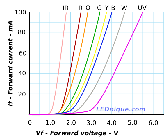
enter image description here

Figure 1. LED current versus voltage for various colours. Source: LED I-V curves.

From the graph we can see that connecting a red LED to a 3.3 V supply would cause the current to go off the chart. A blue LED might survive the experience due to its higher forward voltage, Vf. There's a video I made on the linked page which demonstrates how to draw the graph and you may find it useful.

You might also find Ohm's Law - resistor calculation useful too.


From the comments:

I understand, but the LEDs said their Vf was "1.8-3.4V", so I put that to the test - if they did work @3.3V, I wouldn't need a resistor, is that right?

You've already found that you've blown some due to overvoltage so, no, it's not a good idea.

So my guess was that some colours in their range had a Vf of 3.4 V.

Yes, but at what current and what is the variation? See Variations in Vf and binning for more on this.

Is that graph true for all types of LEDs - all red LEDs are the same?

No. I generated it from datasheets for specific LEDs. We recommend, "No datasheet? No sale!" for reasons that you are learning.

Wouldn't I need to know the max forward current here? (I don't have Vf or Ifmax.)

Yes, but 20 mA is safe for most 3 mm or 5 mm LEDs.

To measure the Vf you can do a simple test.

schematic

simulate this circuit – Schematic created using CircuitLab

Figure 2. A simple Vf measurement circuit. DUT is the "diode under test". VM1 can be your multimeter on V DC range.

The 560 Ω resistor will limit the current through the LED to about 10 mA. (Actually, for a 2 V LED the current will be about 12.5 mA and for a 3.5 V LED the current will be about 9.8 mA. This will be good enough for most purposes.)

\$\endgroup\$
5
  • \$\begingroup\$ I understand, but the LEDs said their Vf was "1.8-3.4V", so I put that to the test - if they did work @3.3V, I wouldn't need a resistor, is that right? So my guess was that some colours in their range had a Vf of 3.4V. Is that graph true for all types of LEDs - all red LEDs are the same? What about these "ultrabright" ones? Wouldn't I need to know the max forward current here (I don't have Vf or Ifmax) \$\endgroup\$ Commented Aug 18, 2019 at 10:04
  • 1
    \$\begingroup\$ @KierenJohnstone: Even if the LEDs light at 3.3V, you cannot rely on that. You must regulate the current to the LED rather than the voltage. \$\endgroup\$
    – JRE
    Commented Aug 18, 2019 at 10:38
  • \$\begingroup\$ @JRE - how would that work? Regulated 3.3V supply, 3.3V LED: voltage across the resistor would need to have 0V sitting across it? \$\endgroup\$ Commented Aug 18, 2019 at 10:47
  • 1
    \$\begingroup\$ A 3.3V LED can't be directly connected to 3.3V. The 3.3V forward voltage is not set in stone. It varies with temperature, and is a little different for each LED. Also, your 3.3V supply is never exactly 3.3V. In one combination it won't light at all (supply a little too low, LED a little to high) and in another combination (supply a little too high, LED a little too low) it will burn out the LED. \$\endgroup\$
    – JRE
    Commented Aug 18, 2019 at 10:52
  • \$\begingroup\$ @Kieren: See the updates. \$\endgroup\$
    – Transistor
    Commented Aug 18, 2019 at 11:59
1
\$\begingroup\$

Please find the datasheet of the LEDs
to start with. The LEDs from same batch probably will have same forward voltage if it is from a reputed distributor (and manufacturer).

For basic operation, you only want to know forward voltage so that you can drive the LED with current limited circuit (simple series resistor for example). The voltage supply you use should be higher than the forward voltage of the LED with some good a few 100 mV of buffer atleast If you want to find out the forward drop of the LED you have, try connecting a 220 ohm resistor in series with the LED and to a 3.3V supply. Measure the voltage drop across the LED with a multimeter. It will give a fair idea. The red LEDs will have lower forward voltage than 3.3V. you can definitely measure the forward voltage.

Please note:

The forward voltage still varies depending on the

  1. the current flowing through the diode
  2. The temperature at which the LED is operating
  3. Different manufacturing batch
\$\endgroup\$
3
  • 1
    \$\begingroup\$ I don't have a datasheet, otherwise I wouldn't need to measure :) I got them from Aliexpress, and the seller hasn't responded to my requests. It sounds like a chicken-and-egg problem: do I use a random resistor and measure something like "a fair idea" of the Vf? The "diode test" function looked great for simply determining, quite precisely, the Vf. Is that the case / how can I replicate that? \$\endgroup\$ Commented Aug 18, 2019 at 10:34
  • \$\begingroup\$ You can test them for your particular application. How much current are you planning? What is the source driving the LEDs? Are they only for the indication or for lighting? \$\endgroup\$
    – User323693
    Commented Aug 18, 2019 at 10:39
  • \$\begingroup\$ @KierenJohnstone You are missing the point. There is little value in measuring the Vf precisely because you are not going to drive the LEDs with a specified voltage. LEDs are current-driven devices...you provide a specified forward current and then measure whatever Vf you get. But you don't design the driver circuit to provide that exact voltage because you must control the current with the understanding that Vf will change a bit. \$\endgroup\$ Commented Aug 18, 2019 at 14:07

Your Answer

By clicking “Post Your Answer”, you agree to our terms of service and acknowledge you have read our privacy policy.

Not the answer you're looking for? Browse other questions tagged or ask your own question.