8
\$\begingroup\$

The general idea is to charge a cordless toothbrush from 12V DC, instead of the mains. I have used a simple circuit that I more or less lifted from a Linear AppNote/Demo manual (DC1969). I would like the circuit to be as simple as possible. The actual transmitter is below, what is not shown is a simple timer that shuts off the thing to conserve power after say 2-3 hours. (The time normally taken to charge).

Prototype 2

I wound a pickup coil with 100 turns and that produced 6V pp 32kHz on the original mains charger. The idea is to create something that produces the same voltage. A 270uH coil (100 turns on the ferrite salvaged form a broken charger) needed only approx 8V to produce 6V so I thought: Transformer, decrease number of turns, but that actually increased the voltage on the pickup coil :) In fact, lowering the inductance of L3 and adjusting C3 increased the current in L3 which naturally will give a higher voltage in the pickup coil.

Now, I am not 100% sure why, but there is a recommendation that L1, L2 should be 5x the inductance of L3, which is clearly not the case here. The purpose of L1, L2 is to act as reservoirs to make sure the circuit acts in current mode, right?

Question is: Is there an optimal way to size L1, L2, L3, given a V1 of 12V? The citcuit works fine now, idle consumption is approx 150mA at 12V, ie 1.8W, whereas the original charger has an idle consumption of 1.2W.

Enquiring minds want to know.

Edit: Based on comments by Russel (below) did I try a centre-tapped coil. This is the waveform with the original circuit.

original circuit waveform

and this is with the centre-tapped version. The idle current draw fell from 0.14A to 0.05A, yay!

center tapped circuit secondar waveform

Too bad I already ordered prototype PCBs, but I guess that is why there are x-acto knives :)

Prototype to give you some idea of the coil sizes. The ferrite is from a scrap brush, but there is one from Amidon that should work quite nicely. The innards of a scrapped brush is in the background to give you an idea of what the original pickup coil looks like.

prototype

\$\endgroup\$
12
  • 2
    \$\begingroup\$ M! M2 form a classic Royer oscillator . L1 L2 are effectively "RFCs" (Radio frequency chokes)(although tgis is rather low frequency for RF.) providing a high impedance load to the FETs blocking the HF from the power supply. Without them the oscillatory waveform is shorted to the power supply. | When impedance of L1 L2 is >> L3 they have reduced affect on the resonance and loading caused by L3. L3 provides the "resonant tank. You could (probably) centre tap L3 and feed DC in there and dispense with L1 L2. \$\endgroup\$
    – Russell McMahon
    Commented Aug 24, 2019 at 11:27
  • \$\begingroup\$ OK. Thanks. I did a simulation and what happens when you increase the values of L1, L2, the frequency approaches the frequency determined by L3, C3 and the current through L1, L2 goes from AC to more of less DC. I will have a peek at the Royer oscillator. \$\endgroup\$
    – AndersG
    Commented Aug 30, 2019 at 13:34
  • 1
    \$\begingroup\$ The/an easy way is to wind two wires together and join the end of one and the start of the other as the centre tap. Suitability of tghis method depends on the application, coil shape etc. Note that if coils are bifilar wound in this way the insulation needs to withstand voltages between adjacent windings which can be high in some cases. \$\endgroup\$
    – Russell McMahon
    Commented Sep 4, 2019 at 12:49
  • 2
    \$\begingroup\$ Notionally (notionally!) the centre tap is at AC ground wrt oscillator and NO RFC is needed. CAREFULLY trying that may be interesting. Conversely, a very large RFC should do no harm apart from any effects from its DC resistance. Power transfer will be very greatly helped by having tx and rx coils at the same frequency. \$\endgroup\$
    – Russell McMahon
    Commented Sep 4, 2019 at 21:38
  • 1
    \$\begingroup\$ @RussellMcMahon re "Notionally (notionally!) the centre tap is at AC ground" , it is at AC ground for the fundamental frequency, but the harmonics are different left and right as one transistor is ON , the other swinging in the breeze. The small inductor in the positive lead of most Royer oscillators is there to suck up the third harmonic, technically it runs the invertor in "current mode", this actually allows both transistors to be on at the same time, as can happen when using low threshold MOSfets. \$\endgroup\$
    – BobT
    Commented Aug 9, 2020 at 10:33

2 Answers 2

1
\$\begingroup\$

My initial question was how the RFCs affect the circuit and why. Thanks to Russel McMahon did i gain a better understanding and realising it was in fact a Royer oscillator led med to the paper linked above that has a similar circuit:

Royer oscillator

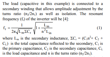
The paper also presents a mathematical model of how the RFCs affect the frequency:

enter image description here

In this case, the term under the root will quickly approach 1 as the value of the RFC increases. This is something that can be clearly seen in my simulations and measurements. By changing to a centre-tapped coil the idle current fell by a factor 3 and I could eliminate one RFC.

The circuit is not ideal. The frequency will change when the circuit is loaded, but the receiver coil is not tuned and all it has to do is to charge an AA NiMH cell in a resonable time. The prototype will have a small timer that starts when the brush is inserted and run for 2-3 hours which is the time it takes to recharge after use.

Thanks again Russel!

Edit: Some additional insight can be had from the Wikipedia article:

A drawback of the voltage mode operation is that the stress on switch transistors is high during the cross over time, when both the voltage and current are high. This drawback is alleviated by using current mode operation. This is achieved by inserting an inductor in the transformer center tap supply. This inductor drops the center tap voltage down when the dI/dt would be very high in voltage mode.

And strictly speaking, if I do not drive the inductor to saturation then it is probably a Baxandall oscillator :)

\$\endgroup\$
0
\$\begingroup\$

At startup all coils are discharged. However, one coil-say L1 charges faster than L2 until the gate shuts the L1 mosfet. At that time L1 fires, the other fet opens and L2 charges fast while L1 recharges slow.

The frequency of this oscillator is determined by the fet gate circuitry. The L1 should charge enough as to fire the L2 as well as to supply the L3 oscillator circuit.

Now the L3 oscillator should be tuned to the fet oscillator. In plus, the energy transferred from L3 to wireless load should be resupplied by either L1 or L2.

So there is a connect between L1/L2 and L3. If they say 5 times the energy storage of L3, I say give it a try see if your overall power draw decreases to 1.2W

But if experimenting further is not an option then you’re pretty much where you’re supposed to be.

\$\endgroup\$

Your Answer

By clicking “Post Your Answer”, you agree to our terms of service and acknowledge you have read our privacy policy.

Not the answer you're looking for? Browse other questions tagged or ask your own question.