0
\$\begingroup\$

schematic

simulate this circuit – Schematic created using CircuitLab

I have to calculate the energy of the inductors magnetic field at t = 6 ms.

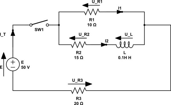
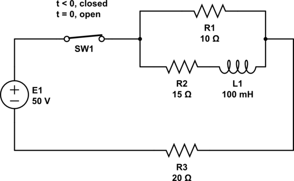
I am given: E = 50 V, R1 = 10 Ω, R2 = 15 Ω, R3 = 20 Ω and L = 0.1 H


So at t < 0, the switch is closed and the current is flowing. In the parallel section, we get I1 and I2, since the inductor formula is time-dependent and it is t < 0 the inductor will have no voltage and will behave like a wire.

I calculate the total resistance in the parallel and add R3 for Rtotal;

$$ R_{total} = (\frac{1}{R_1} + \frac{1}{R_2})^{-1} + R_3 = 26 Ω $$

$$ I = \frac{U}{R_{total}} = \frac{50}{26} = 1.92 A $$

Now I can calculate the voltages in the circuit parts;

$$ U_{R3} = I * R_3 = 1.92 * 20 = 38.40 V $$

The voltage in parallel should be the same so UR1 = UR2 and together with UR3 should amount to 50 V, 50 - 38.40 = 11.60V in parallel.

At t = 0 the switch is open. The current stops flowing from the source and the depletion of the inductor starts.

It is a falling function the only voltage provider is the inductor;

$$ I = \frac{U_L}{R_1 + R_2} \rightarrow 1.92 = \frac{U_L}{25} \rightarrow U_L = 48 V $$

So since it is t = 0 things will remain the same;

$$ I_L = 1.92 \exp{\frac{-0}{\tau}} = 1.92 A $$

$$ U_L = 48 \exp{\frac{-0}{\tau}} = 48 V $$

At t = 6ms = 0.006 s;

$$ \tau = \frac{L}{R_{total}} = \frac{0.1}{25} = 0.004 $$

$$ I_L = 1.92\exp{\frac{-0.006}{0.004}} = 0.42 A $$

$$ U_L = 48\exp{\frac{-0.006}{0.004}} = 10.71 V $$

The energy of the inductor at t = 6 ms;

$$ W_L = \frac{Li^2}{2} = \frac{0.1 * 0.42^2}{2} = 0.008 J $$

\$\endgroup\$
8
  • 1
    \$\begingroup\$ I think it's useful to think of an inductor as a form of current source instead of voltage, because "it tries" to keep the current steady. And if you think about the current which is going to flow, which of the three resistors is/are in the current path when the switch opens? \$\endgroup\$
    – Arsenal
    Commented Aug 29, 2019 at 12:48
  • \$\begingroup\$ So the current goes thru R1 and R2 only it won go thru R3=20Ω \$\endgroup\$
    – make2r
    Commented Aug 29, 2019 at 12:55
  • \$\begingroup\$ Yes that is correct. \$\endgroup\$
    – Arsenal
    Commented Aug 29, 2019 at 12:59
  • \$\begingroup\$ so I=UL/Rtotal -> 1.92=UL/25 -> UL=48V Tau=L/Rtotal=0.1/25=0.004 , iL=1.92*e^(-0.006/0.004)=0.42A , uL=48*e^(-0.006/0.004)=10.71V , energy of the inductor at t=6ms WL=(L*i^2)/2=0.008J \$\endgroup\$
    – make2r
    Commented Aug 29, 2019 at 13:06
  • 1
    \$\begingroup\$ Your diagram should indicate which is R1, R2 etc.. Don't expect folk to keep glancing up and down because it drives me mad doing that and you don't want to get me mad. \$\endgroup\$
    – Andy aka
    Commented Aug 29, 2019 at 13:10

1 Answer 1

0
\$\begingroup\$

At t < 0:

The switch is closed and the current is flowing. We assume that the system has reach the stationary phase. So, the inductor (its formula is time-dependent) the inductor will have no voltage and will behave like a wire.

schematic

simulate this circuit – Schematic created using CircuitLab

You calculated the total resistance for this circuit:

$$ R_{total} = (\frac{1}{R_1} + \frac{1}{R_2})^{-1} + R_3 ≃ 26 Ω $$ Which leads to: $$ I_T = \frac{U}{R_{total}} = \frac{50}{26} ≃ 1.92 A $$ Now, you can calculate the voltages and currents through the circuit: $$ U_{R3} = I_T*R_{3} = 1.92 *20 ≃ 38.40V $$ The voltage in parallel should be the same so UR1 = UR2. Together with UR3 should amount to 50 V, UR1 = UR2 = 50 - 38.40 = 11.60V in parallel.

With ohm law, you can determine the currents going through the resistor and deduce the current going through the inductor:

$$ U_{R1} = R_{1} * i_{1} => I_{1} ≃ 1.15A $$ $$ U_{R2} = R_{2} * i_{2} => I_{2} ≃ 0.77A $$

Resistor R2 and inductor L are components in serie:

But $$ I_{R_2} = I_L ≃ 0.77A $$

At t = 0 :

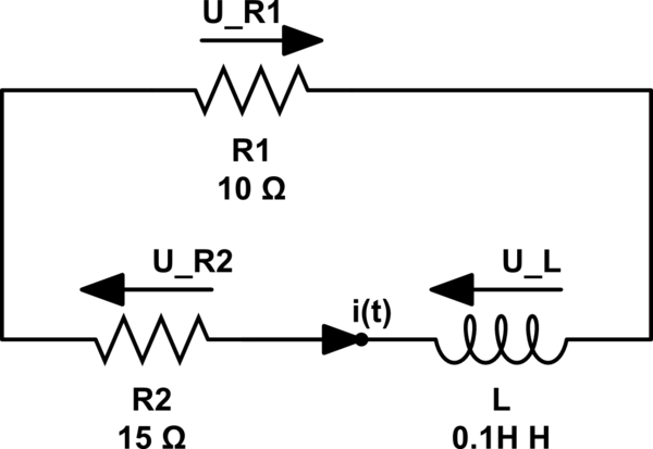
The switch is open. The current stops flowing from the source and the depletion of the inductor starts.

schematic

simulate this circuit

You will notice that I change the convention of the voltage for the resistor R1 in order to keep the voltage arrow of R1 in the "oposite direction" of the current arrow going through R1.

It is a falling function the only voltage provider is the inductor. It comes from the differential equation of the circuit:

Use the Kirchhoff law for meshes: $$ U_{L} + U_{R1} + U_{R2} = 0 $$ But, you know that, for an inductor, $$ U_{L} = L\frac{di(t)}{dt} $$ with i(t) the current going through the inductor !

The ohm law gives you: $$ U_{R1} = R_{1} * i(t) $$ and $$ U_{R2} = R_{2} * i(t) $$ This leads to: $$ L\frac{di(t)}{dt} + R_{1} * i(t) + R_{2} * i(t) = 0 $$ The solution of this differential equation is: $$ i(t) = cst*e^{ \frac{-t}{tau} } $$ with cst to be determined and tau the characteristic time of your circuit for t>0 with $$ tau = \frac{L}{R_{1}+R_{2}} = 0.004s $$ (this is math)

Now, (this is your mistake), you have to find cst, for that you know that the current flowing an inductor is continuous, so:

$$ i(t = 0^{-}) = i(t = 0^{+}) $$ Or $$ i(t = 0^{-}) = I_L ≃ 0.77A ≠ 1.92 A !$$

Consequently, you have: $$ i(t) = 0.77*e^{ \frac{-t}{0.004} } $$

Which leads you to t=6ms: $$ i(t) = 0.77*e^{ \frac{-0.006}{0.004} } ≃ 0.17A $$

So: The energy of the inductor at t = 6 ms is: $$ W(t=6ms) = \frac{L*(i(t=6ms))^2}{2} = \frac{0.1*0.17^2}{2} ≃ 0.0015J $$

\$\endgroup\$

Your Answer

By clicking “Post Your Answer”, you agree to our terms of service and acknowledge you have read our privacy policy.

Not the answer you're looking for? Browse other questions tagged or ask your own question.