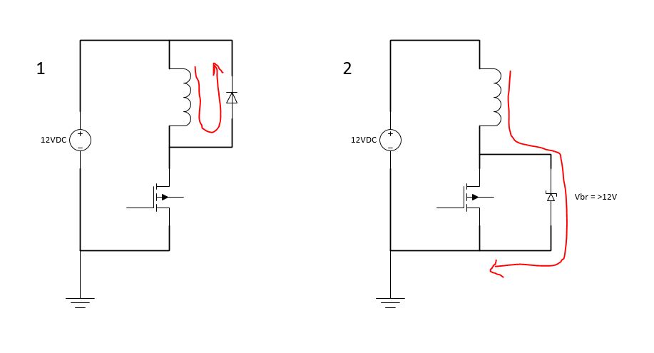
In literature we commonly see the use of a freewheel diode to protect the circuit against the inductive kick when the switch goes from closed to open (Fig 1). However, what would be the pros/cons of discharging the energy to ground through say a Zener diode (Fig 2)? I have never seen this in practice and I wonder why.
-
1\$\begingroup\$ For the freewheel diode, it should be an avalanche type for more reliable operation. \$\endgroup\$– Peter MortensenCommented Aug 31, 2019 at 1:07
-
1\$\begingroup\$ Shameless plug \$\endgroup\$– LorenzoDonati4Ukraine-OnStrikeCommented Aug 31, 2019 at 16:47
5 Answers
It's frequently used in applications such as actuation of fuel injection solenoids where it's important to collapse the magnetic field as fast as possible.
Edit: See, for example, the LM1949 fuel injector driver IC which shows an external 33V 5W zener diode. Typical 'on' timing is 2.5 to 3.5ms, and a typical inductance is in the ~2mH range.
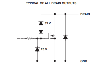
It's also possible to use an avalanche-rated MOSFET or add a zener from MOSFET drain to gate in order to cause clamping at a predetermined voltage. See, for example, TI's TPIC6C595 power shift register. One big advantage in this particular case is that it saves a pin on the IC.
Since more of the energy is dissipated in an active device, this is harder on the switching circuit. When you use a diode, most of the energy is lost in the coil resistance and only a small amount is lost in the diode.
You can also simply add a resistor in series with the normal flyback diode. Since the peak current is the same as the current prior to switching off, the peak voltage will be the supply voltage plus a diode drop plus the current times the series resistance. The diode is not necessary for the purpose of limiting the voltage, but it prevents the resistor from dissipating power while the coil is energized.
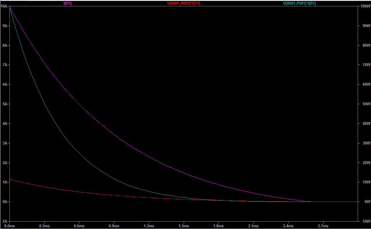
Edit: (below is a simulation of 1mH inductance with 1 ohm series resistance and 10A rectifier, shortly after 10A current is switched off)
Pink trace is diode current, cyan trace is power in the coil resistance, red trace is power in the diode. Force of a solenoid will be more-or-less proportional to the coil (and thus diode) current (pink trace).
Integrated energy for the rectifier: 7.7681mJ Integrated energy for the coil: 41.844mJ
As a check, the total energy stored in the magnetic field is obviously 50mJ, and the two add up to 49.6mJ, pretty close. I've used a real MOSFET model for the switch
By comparison if you remove the diode and add a 36V zener across the transistor, the current drops to zero in about 350us rather than 2.5ms, a 7:1 improvement, but the zener sees a peak power of 360W and absorbs most of the stored energy.
-
1\$\begingroup\$ How long are fuel injection solenoids open for and how slow is the collapse which makes it too slow? \$\endgroup\$– DKNguyenCommented Aug 30, 2019 at 16:21
-
1\$\begingroup\$ @DKNguyen LR time constant is similar to the timing, see edit. Eg. 1 ohm and 2mH. \$\endgroup\$ Commented Aug 30, 2019 at 16:50
Compared to (1) where the diode conducts in the forward direction, the zener diode in (2) breaks down in reverse to present a larger voltage drop to the inductor which it act as a power source when it kicks. This drains energy from the magnetic field more rapidly and therefore collapses it more quickly.
My understanding is this helps solenoids reset faster (because it kills the magnetic field holding the solenoid faster) but seems like a needless waste of energy in PWM scenarios since you're just dumping all the energy stored in the magnetic field only to immediately build it up again. Like rushing up to a red light and slamming on the brakes only to accelerate again from zero rather than coasting to the red light so you still have some momentum when the light turns green
-
\$\begingroup\$ I think that schottky diodes that are usually used as freewheel diodes are faster than zeners, aren't they? \$\endgroup\$– MrBitCommented Aug 30, 2019 at 16:03
-
4\$\begingroup\$ The point isn't that the diode is faster. The point is that by putting a higher voltage on the inductor in opposition to the current, the inductor current diminishes faster -- remember that in an inductor, \$di / dt = v/L\$. Increase the voltage, and you increase the rate of change in current. \$\endgroup\$ Commented Aug 30, 2019 at 16:05
-
2\$\begingroup\$ I don't know if a schotky entering conduction is faster than a zener breaking down in reverse, but schotkys are faster entering forward conduction than other types and have a softer recovery which is why they are used. \$\endgroup\$– DKNguyenCommented Aug 30, 2019 at 16:06
-
1\$\begingroup\$ @BigAl say switching a motor (or a buck converter), why dump the energy in the magnetic field as heat only to build it up again if some of it can be allowed to remain at the start of the next switching cycle? \$\endgroup\$– DKNguyenCommented Aug 30, 2019 at 16:07
-
2\$\begingroup\$ Reverse breakdown is pretty quick. A zener diode may have a pretty ordinary reverse recovery time, but it'll still start conducting in reverse astonishingly fast. And I apologize for such vaguely-dimensioned terms as "astonishingly fast": I don't know the exact numbers. But it's plenty fast for this purpose. \$\endgroup\$ Commented Aug 30, 2019 at 16:12
One difference that could be significant is that in Fig 2 the discharge current flows through the power supply, increasing total energy draw but also slowing down the supply current change.
If the coil is switched on and off often then Fig 2 could double the power consumption. This is not a good solution when using PWM.
On the other hand, the diode in Fig. 1 quenches back emf voltage across the coil itself, but not in the wiring going to it. If the power wires are long they could have significant inductance. The fast supply current drop that occurs at switch off could induce a high voltage spike that stresses the switching transistor.
So in a circuit that switches the coil off infrequently, Fig 2 could provide better protection for the transistor with fewer parts. Another possible advantage is that you don't need to add a diode across a coil which might be in a hard to reach remote location.
It depends on what the coil is for and what you want it to do. For relays, a 100 ohm resistor is often placed across the coil to dampen the energy yet permits the relay to open/close quickly. If the coil is part of an actuator and the coil is pulse width modulated, then a diode is placed across it like you have shown. If you connect the zener to ground the inductive voltage will rise until the zener clamps it. Try modeling the circuit in LT Spice (it's free) and see what happens.
The length of time that the current in the inductor takes to drop to zero can be reduced be placing either a resistor or a Zener in series with the usually seen freewheel diode.
The usually seen freewheel diode is still required because it stops conduction through the resistor or forward biased Zener when the transistor is on.
The resistor's value would be calculated by considering the resistor's maximum current (equal to the inductor current when the transistor is switched on) and the transistor's maximum Vce rating. The maximum induced voltage generated across the resistor would then be limited (by choosing the resistor's value) to Vce(max) - Vsupply. This then, because di/dt = V/L, enables the fastest decay of inductor current with the added resistor technique.
To enable an even faster decay of current. a zener is added (rather than a resistor). The Zener controlled current reduction rate is faster than the added resistor reduction rate because the Zener holds the induced back emf constant (over much of the current decay period) and therefore the current decays in a linear manner (faster manner) with the added resistor technique the induced back emf is not held constant, it decays exponentially. Therefore the inductor's current also decays exponentially which means it takes longer to decay to zero.
So, to summarise - The freewheel diode on its own is the slowest, the added resistor faster and the added Zener even faster.


