6
\$\begingroup\$

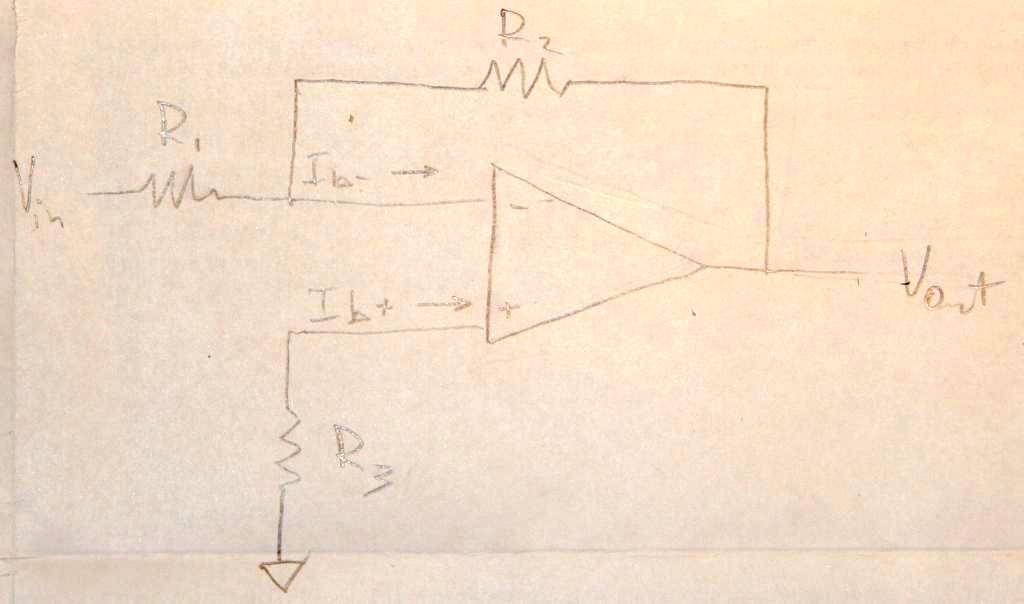
Essentially I am getting confused trying to do the sums for an op amp with a gain of 10dB and an input impedance of 1kohm.

I worked out that \$\frac{V_{out}}{V_{in}}=-\frac{R_{2}}{R_{1}}\$ because \$V_{+}\$was going to ground, \$=>V_{-}=0\$.

I know that the output impedance of the amplifier itself is very high.

I know that the compensation resistance \$R_{3}=\frac{R_1R_2}{(R_1+R_2)}\$ but I am not certain why.

I had thought the input impedance would be the \$R_1||R_2\$ (or whatever else would go to the node for \$V_-\$ which in this case is just \$R_1\$ and \$R_2\$) but I am doubting myself.

Can anyone clarify what this input impedance is actually referring to?

inverting op amp picture

I should also perhaps add that I am going to construct this for real out of a 741 amplifier so I am trying to figure out what resistances to pick to get my 1000 \$\Omega\$. I can't believe that \$R_2\$ wouldn't matter in this, so if anyone can clarify that, it would be useful.

\$\endgroup\$
8
  • \$\begingroup\$ Re: picture. Upload the picture to some hosing on the web (flickr and such). Edit your post and add a link to the picture. Somebody with enough rep will edit your post (again) and inline the picture. \$\endgroup\$ Commented Oct 29, 2012 at 1:04
  • \$\begingroup\$ Are you trying to get a better understanding of why compensation resistor \$R_{3}=\frac{R_1R_2}{(R_1+R_2)}=R_1||R_2\$ ? \$\endgroup\$ Commented Oct 29, 2012 at 1:38
  • 1
    \$\begingroup\$ Because they are cheap and it is just for learning purposes. \$\endgroup\$
    – Magpie
    Commented Oct 29, 2012 at 2:51
  • 1
    \$\begingroup\$ @NickAlexeev - But there's better op-amps for that too! Besides, it's easier to start with a device where you don't really need to worry about input bias currents, etc..., at least until you have a decent grasp of the basics. \$\endgroup\$ Commented Oct 29, 2012 at 3:01
  • 2
    \$\begingroup\$ "I know that the output impedance of the amplifier itself is very high." output impedance is low, not high. \$\endgroup\$
    – endolith
    Commented Jun 11, 2015 at 16:08

4 Answers 4

7
\$\begingroup\$

@DaveTweed wrote a good verbal proof for \$R_{3}=\dfrac{R_1R_2}{R_1+R_2}=R_1||R_2\$.
Here's an algebraic version.

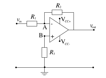
Let's drop the ideal op-amp assumption that op-amp input currents \$I_{b+}\$ and \$I_{b-}\$ are zero.

\$I_b=I_{b+}=I_{b-}\neq0\$

In practice, \$I_b\$ can vary between different batches of ICs. \$I_b\$ isn't known. Let's assume that it's fixed.
enter image description here

First, consider the case without compensation resistor, \$R_3=0\$.

\$\dfrac{V_{in}}{R_1}+\dfrac{V_{out}}{R_2}+I_b =0\$,

\$V_{out}=-V_{in}\dfrac{R_2}{R_1}-I_bR_2\$

Notice the \$I_b R_2\$ nuisance.

Second, consider \$R_3\neq0\$. Let's find \$R_3\$ such that \$V_{out}\$ is closest to \$-V_{in}\dfrac{R_2}{R_1}\$

Voltage at the positive input: \$V_{(+)}=I_bR_3\$

\$\dfrac{V_{in}-I_bR_3}{R_1}+\dfrac{V_{out}-I_bR_3}{R_2}+I_b=0\$

\$\dfrac{V_{in}}{R_1}+\dfrac{V_{out}}{R_2}+I_b\left(\dfrac{R_3}{R_1}+\dfrac{R_3}{R_2}-1 \right)=0\$

Notice the \$I_b\left(\dfrac{R_3}{R_1}+\dfrac{R_3}{R_2}-1 \right)\$ nuisance. Let's equate it to 0 and solve for \$ R_3 \$.

\$I_b\left(\dfrac{R_3}{R_1}+\dfrac{R_3}{R_2}-1 \right)=0\$, when \$\dfrac{R_3}{R_1}+\dfrac{R_3}{R_2}=1\$

which can be solved for \$R_{3}=\dfrac{R_1R_2}{R_1+R_2}=R_1||R_2\$

Extra:

I made an assumption that \$ I_{b+}=I_{b-} \$ (the input currents are equal).
How good is this assumption?

The average of the input currents is called the input bias current \$ I_b = \dfrac{I_{b+} + I_{b-}}{2} \$, and the difference is called input offset current \$ I_{OS} = I_{b+} - I_{b-}\$.

\$ I_b\$ and \$ I_{OS}\$ are mentioned in the datasheets. Usually \$ I_{OS}\$ is significantly smaller than \$ I_b\$. For example, LM324 has \$ I_b\$ = -60 nA max and \$ I_{OS}\$ = ±5 nA max.

The output error due to input currents

\$ E_O = \left(1 + \cfrac{R_2}{R_1} \right) \left( \left( R_1 || R_2 \right) I_{b-} - R_3 I_{b+} \right) \$

Substituting \$ I_{b+} = I_b + \cfrac{I_{OS}}{2}\$ and \$ I_{b-} = I_b - \cfrac{I_{OS}}{2}\$ , then factoring out \$ I_b\$ and \$ I_{OS}\$ .

\$ E_O = \left(1 + \cfrac{R_2}{R_1} \right) \left( \left( \left( R_1 || R_2 \right) - R_3 \right) I_b - \cfrac{1}{2} \left( \left( R_1 || R_2 \right) + R_3 \right) I_{OS} \right) \$

Like before we choose \$ R_3 = R_1 || R_2\$ .

The \$ I_b\$ term collapses and the error reduces to

\$ E_O = \left(1 + \cfrac{R_2}{R_1} \right) \left( - R_1 || R_2 \right) I_{OS} \$

The error can be reduced further by reducing the values of \$ R_1\$ and \$ R_2\$ while
preserving the ratio \$ R_2 / R_1\$ .
\$\endgroup\$
5
  • 1
    \$\begingroup\$ Thanks that helped further clarify the second part of my question. Though I still don't get what the definition of input impedance is? \$\endgroup\$
    – Magpie
    Commented Oct 29, 2012 at 3:02
  • 1
    \$\begingroup\$ @Magpie, the input resistance is, in words, the equivalent resistance seen by the source driving the input of the circuit. In this circuit, it is the ratio of \$v_{in}\$ to the current entering \$R_1\$ In other words, it is the Thevenin equivalent resistance looking into the two left most terminals in your schematic. \$\endgroup\$ Commented Oct 29, 2012 at 3:07
  • \$\begingroup\$ So if I pick \$R_1\$ to be \$1000\Omega\$ then \$R_2{2}\$ is simply the value for which its ratio would give me a gain of 10dB? \$\endgroup\$
    – Magpie
    Commented Oct 29, 2012 at 3:13
  • \$\begingroup\$ @Magpie I think, you're correct. 10dB in the O.P. sounds like a closed loop gain. 10dB is an awfully small number for an open loop gain. Even for a 741. \$\endgroup\$ Commented Oct 29, 2012 at 3:26
  • \$\begingroup\$ Sorry, it should have been this one. I ticked I had overlooked the bit about the input impedance had been answered in the comments too. It would be good if it was in the answer but overall this one is more complete. \$\endgroup\$
    – Magpie
    Commented Oct 29, 2012 at 12:32
7
\$\begingroup\$

I had thought the input impedance would be the R1||R2 (or whatever else would go to the node for V− which in this case is just R1 and R2) but I am doubting myself.

Can anyone clarify what this input impedance is actually referring to?

For an ideal opamp, there is no current into the input terminals. Thus, the voltage across \$R_3 \$ is \$v_{R3} = 0 \rightarrow v_B = 0 \$.

Since there is negative feedback, \$v_A = v_B = 0\$.

So, the entire input voltage, \$v_{in}\$, appears across \$ R_1 \$.

Thus, the input resistance must equal the value of \$R_1 \$.

\$R_{IN} = \dfrac{v_{in}}{i_{in}} = \dfrac{v_{in}}{v_{in}/R_1} = R_1\$

Update due to edit of question:

I suspect you might be confused by two very different resistances.

The input resistance is simply the ratio of the input voltage to the input current:

\$R_{IN} = \dfrac{v_{in}}{i_{in}} \$

The resistance seen by (looking out of) the inverting terminal is \$R_1 || R_2 \$.

This is why \$R_3 = R_1 || R_2\$ if you want the resistances attached to the input terminals to be equal.

I can't believe that R2 wouldn't matter in this, so if anyone can clarify that, it would be useful.

Why? It's basic opamp theory.

enter image description here

\$\endgroup\$
11
  • \$\begingroup\$ what about \$R_2\$? \$\endgroup\$
    – Magpie
    Commented Oct 29, 2012 at 1:28
  • 1
    \$\begingroup\$ The input impedance is \$R_1\$. \$R_2\$ doesn't matter as long as it is non-zero and finite for the reason that the voltage at node A is zero (for an ideal opamp) regardless of \$R_2\$. This is opamp 101 stuff. I can add a reference or three if you think it is needed. \$\endgroup\$ Commented Oct 29, 2012 at 1:37
  • 2
    \$\begingroup\$ @NickAlexeev, the OP has written that the inverting terminal voltage is zero which is how the gain was derived. Under that assumption, that \$v_- = 0 \$, \$R_2\$ is not a factor in the input resistance. Moreover, as long as the open-loop gain is very large such that the constraint is effectively true, the input resistance is effectively \$R_1\$ \$\endgroup\$ Commented Oct 29, 2012 at 2:03
  • 1
    \$\begingroup\$ @Alfred-centauri has given you the correct answer. Remember that the inverting input will be at a virtual ground. \$\endgroup\$ Commented Oct 29, 2012 at 2:31
  • 3
    \$\begingroup\$ Why was this voted down? It's the correct answer (at least as I understand the question). \$\endgroup\$ Commented Oct 29, 2012 at 2:47
3
\$\begingroup\$

The "compensation" resistance R3 equals the parallel combination of R1 and R2 because the far end of each of those resistors is presumed to be connected to a voltage source. Each of those sources has essentially zero resistance to ground, so any bias current at the V- input to the opamp flows through the parallel combination of the two resistors.

In order to minimize the voltage offset that is due to that bias current, you want to have the same effective resistance at the V+ input. This presumes, of course, that if the two inputs are at the same voltage, they have the same bias current.

\$\endgroup\$
3
  • \$\begingroup\$ Does that mean I was right to think the input impedance is \$R_1||R_2\$, since it is the resistance into \$V_-\$ that is considered? \$\endgroup\$
    – Magpie
    Commented Oct 29, 2012 at 1:35
  • \$\begingroup\$ The principal analysis that needs to be understood is a small signal analysis. In doing so all voltage sources and driven outputs turn in small signal grounds and the analysis follows from that. \$\endgroup\$ Commented Oct 29, 2012 at 2:32
  • \$\begingroup\$ @Magpie: No, the input resistance is R1, as Alfred Centauri explained in his answer. I was just addressing your other question. \$\endgroup\$
    – Dave Tweed
    Commented Oct 29, 2012 at 11:21
1
\$\begingroup\$

<<< I know that the output impedance of the amplifier itself is very high.>>>

This is false. It is very "low".

To calculate it, just apply the definition :

\$Zout = Vout(output,open)/Iout(output,shorted)\$

Here using TRAN analysis -> measured ... 1.2 mOhm

enter image description here

Using AC Analysis -> measured (2.45-1.2) mOhm = 1.25 mOhm. Confirmed.

enter image description here

\$\endgroup\$

Your Answer

By clicking “Post Your Answer”, you agree to our terms of service and acknowledge you have read our privacy policy.

Not the answer you're looking for? Browse other questions tagged or ask your own question.