1
\$\begingroup\$

I am trying to follow some guides (for instance this) to generate some analog signals (for instance a sine wave of 50 Hz) with Arduino (but my questions are general).

But I have two basic questions:

1) The author of the guide chooses to generate that sine wave starting from a PWM signal of 31372Hz. As I understood, it is possible to choose an arbitrary frequency (with some limits obviously) since it is determined by some settings on the MCU internal timers. How do we choose it? Does its choice depend on the low - pass filter we decide to apply?

2) The guide shows the procedure for generating the first half wave on a pin, and the second half wave on another pin. Then, the voltage difference between them is taken, with a circuit called "H bridge". Is there any method to generate the full waveform directly on a single pin?

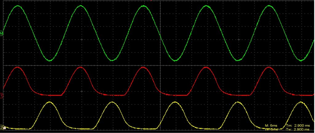
enter image description here

\$\endgroup\$

1 Answer 1

3
\$\begingroup\$

Secrets of Arduino PWM should answer most of your questions but you might need to read it a couple of times. It says:

Each of the timers has a prescaler that generates the timer clock by dividing the system clock by a prescale factor such as 1, 8, 64, 256, or 1024. The Arduino has a system clock of 16 MHz and the timer clock frequency will be the system clock frequency divided by the prescale factor. Note that Timer 2 has a different set of prescale values from the other timers.

That means that you are limited in the chosen value. You can get the PWM counters to reset at a value lower than 256 but then you lose PWM resolution.

As I understood, it is possible to choose an arbitrary frequency (with some limits obviously) since it is determined by some settings on the MCU internal timers. How do we choose it? Does its choice depend on the low - pass filter we decide to apply?

The first sentence is correct as discussed already.

enter image description here

Figure 1. PWM for sinewave generation. Note that the PWM waveform is shown as a relatively low frequency for illustrative purposes. In practice it would need to be a couple of orders of magnitude of frequency higher than the sinewave to be produced. Source: How is a PWM signal converted to Sine using a transformer?.

The second sentence is also correct. The filter on the PWM output has to filter out all the higher frequencies of the PWM if you hope to get a smooth sine.

Is there any method to generate the full waveform directly on a single pin?
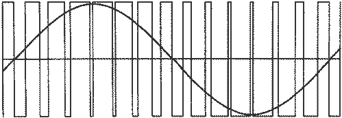
Yes, but since the PWM is switching between 0 V and 5 V (or 3.3 V as the case may be) you have to bias the 'zero' of the sine to half supply or some other positive voltage.

\$\endgroup\$
3
  • \$\begingroup\$ Perfect, there is only a last doubt about when you say "You can get the PWM counters to reset at a value lower than 256 but then you lose PWM resolution". How is the PWM resolution related to the choice of frequency? I thought that the resolution was related only on the number of bits of the timer. \$\endgroup\$
    – Kinka-Byo
    Commented Sep 13, 2019 at 20:41
  • \$\begingroup\$ It is, but if you need, for some reason, to generate a PWM at a particular frequency and the only way to do it is to reset the PWM counter a bit early to raise the frequency. If you reset at, say, 200 instead of letting it run to 256 then you've reduced the PWM resolution by a little more than 20%. \$\endgroup\$
    – Transistor
    Commented Sep 13, 2019 at 20:50
  • \$\begingroup\$ Perfect, thank you very much \$\endgroup\$
    – Kinka-Byo
    Commented Sep 13, 2019 at 20:59

Your Answer

By clicking “Post Your Answer”, you agree to our terms of service and acknowledge you have read our privacy policy.

Not the answer you're looking for? Browse other questions tagged or ask your own question.