0
\$\begingroup\$

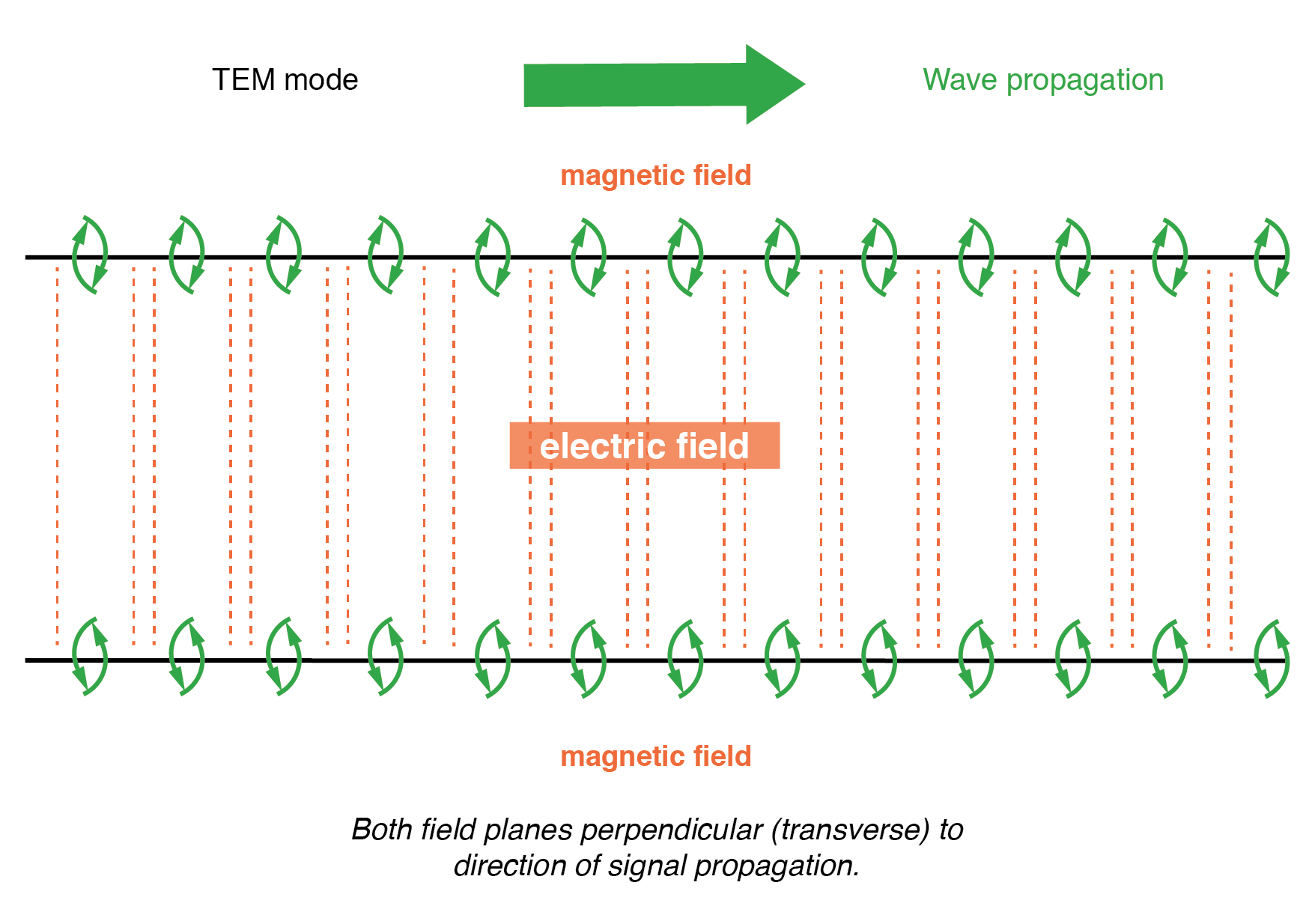
let's consider this image (from AAC book, see here)

enter image description here

The author wanted to show that a transmission line propagates not only voltage and current waves, but also an electromagnetic wave in the space between its 2 conductors.

But I have a question: from the image I think that the magnetic field shown is that generated by the wire, but how is the electric field? From the image I do not see its direction, if it is rotational or not, and I do not understand if it is the electric field generated by the voltage applied to the transmission line (since voltage between two points = electric field) or the electric field generated by the variation in time of the magnetic field represented in green.

\$\endgroup\$
8
  • \$\begingroup\$ What kind of waveguide or tranmission line are we talking about, the fields vary with construction and geometery \$\endgroup\$
    – Voltage Spike
    Commented Sep 19, 2019 at 22:17
  • \$\begingroup\$ But is the electric field that generated by the voltage applied to the line, or that generated by the variation of the magnetic field, or a sum of both? \$\endgroup\$
    – Kinka-Byo
    Commented Sep 20, 2019 at 1:20
  • \$\begingroup\$ The voltage between the lines, and the electric field pointing from one to the other are just two ways of measuring the same phenomenon. You can't say one causes the other. \$\endgroup\$
    – The Photon
    Commented Sep 20, 2019 at 2:15
  • \$\begingroup\$ And as with all EM waves, the changing magnetic field "causes" the electric field to change; and the changing electric field "causes" the magnetic field to change --- leading to a self-propagating wave. The I and V in the transmission line's conductors are just a different way of describing the same behavior. \$\endgroup\$
    – The Photon
    Commented Sep 20, 2019 at 2:16
  • \$\begingroup\$ Perfect, all clear. Thank you very much. \$\endgroup\$
    – Kinka-Byo
    Commented Sep 20, 2019 at 5:35

2 Answers 2

1
\$\begingroup\$

The magnetic field around the wire corresponds to the current in the wire. More correctly, the magnetic field in the space between the wires corresponds to the current loop formed by the source, one wire, the sink, and the other wire.

The electric field between the wires corresponds to the voltage between the wires. If there's 10v measured between the wires, and a distance of 1m between them, then the field will be about 10v/m (varies with the position), with a conventional direction of from the positive conductor to the negative conductor. The direction isn't shown on your diagram, perhaps to avoid clutter, perhaps because the author thought it was obvious.

It's common to hear transmission lines described as wave guiding structures.

\$\endgroup\$
3
  • \$\begingroup\$ Perfect, thank you very much. Only a last question: when you say that the electric field between the wires vary with the position, which is the reason for this non - uniformity? Moreover, is it maximum at the centre of the space between the wires? \$\endgroup\$
    – Kinka-Byo
    Commented Sep 20, 2019 at 5:41
  • \$\begingroup\$ @Kinka-Byo Good question. It depends on the geometry of the space between the conductors. If the 'wires' were wide strips, then the field would be more or less uniform in the space between them, and fall off beyond the edges. With wires, and the effect is especially noticeable with small diameter ones, the field will be maximum at the highly curved surface of the wire. Have a look at this. \$\endgroup\$
    – Neil_UK
    Commented Sep 20, 2019 at 7:06
  • \$\begingroup\$ Ok, all clear! Thank you \$\endgroup\$
    – Kinka-Byo
    Commented Sep 20, 2019 at 7:34
0
\$\begingroup\$

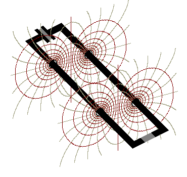
For a 2-wire transmission line (antenna lead-in wires, but also a DC flashlight, or a 60Hz lamp-cord,) the fields in 3-dimensions look more like this below, where the red lines are the magnetic field, and the gray lines are the e-field.
enter image description here

Above, the field-pattern for only two planes is depicted, while in reality, there is a stack of infinitely many such planes. Refer to your textbook diagram, and you'll see that yours is a simplified "side view" of the fully 3D version. We treat the two wires as capacitor-plates having opposite charge. Also, we treat the two wires as part of a 1-turn electromagnet (a long, rectangle-shaped loop.) Multiplying the fields together as vector cross-product gives the power-density at any point in space ...or multiplying voltage by amp-turns (for 1-turn loop) gives the total energy flow: watts.

For a disconnected pair of wires, there would be zero current, but significant voltage and e-field, with no energy-flow. That's the electrostatic case for circuits: voltage without current.

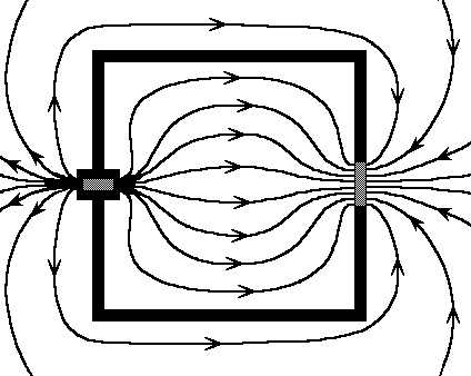
Or, for a superconductor rectangle loop, there would be zero voltage, but significant current and b-field, with no energy flow. That's the magnetostatic case. Next, add a resistor-load to the loop, and also insert an energy-source, and then we have both voltage and current together (the cross-product of e-field with b-field,) which produces a one-way energy-flux from the power supply and into the resistor. Like this below:
enter image description here

  • E-cross-B, the energy-flux or "Poynting field" in 3D

Notice that there is no lower limit to the frequency. The description applies both to the GHz 2-wire lines, as well as battery-powered DC circuits. (Most textbooks miss this important point. Transmission-line theory applies to flashlights and washing machines! Kraus "Electromagnetics" is one book which gets it right.) Even at DC, with waves of "infinite wavelength," the energy-flow is still parallel to the wires, while the e-field and b-field vectors are everywhere at 90deg. (Or, imagine 60Hz waves many thousands of miles long. In the center of each "lump" of traveling 60Hz radiation, the fields are perpendicular, and the energy is flowing parallel to the two wires.) It's not the EM waves which are transverse, it's the very field-vectors themselves which are transverse, even at DC with no waves apparent. Electric circuits are both inductors and capacitors at once, and that's why EM energy can propagate across them.

An electric circuit with a source and a load, and with an energy-flow propagating between the two ...it's a unique electronic component: a kind of "coil-pacitor!"

\$\endgroup\$
1
  • \$\begingroup\$ Thank you for the explanation. All clear. These two images are perfect! \$\endgroup\$
    – Kinka-Byo
    Commented Sep 20, 2019 at 10:43

Your Answer

By clicking “Post Your Answer”, you agree to our terms of service and acknowledge you have read our privacy policy.

Not the answer you're looking for? Browse other questions tagged or ask your own question.