0
\$\begingroup\$

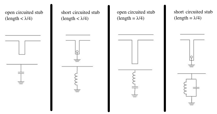
Do anyone know how to derive the microstrip stub equations for all four microstrip below ?
1

\$\endgroup\$
2
  • \$\begingroup\$ Start with these basics ee.scu.edu/eefac/healy/char.html \$\endgroup\$
    – D.A.S.
    Commented Sep 25, 2019 at 1:04
  • \$\begingroup\$ basically you are using stubs as impedance transformers; what is the input impedance of a quarter-wave stub with the far end being grounded? \$\endgroup\$ Commented Sep 25, 2019 at 3:49

1 Answer 1

2
\$\begingroup\$

Impedance of a transmission line v. frequency

Stolen from: https://www.edn.com/design/test-and-measurement/4424529/So-you-think-you-understand-transmission-lines-

But anyways, that's the impedance of some transmission line that's open on the other end. You can see it decreases in impedance initially, which is the hallmark of a capacitor. Then it sharply decreases and starts going back up, which is a resonance and can be modeled by a inductor in series with the capacitor.

If you look at the impedance of a transmission line:

$$ Z_{in}(l) = Z_0 \frac {Z_L + jZ_0 \tan(\beta l)} {Z_0 + jZ_L \tan(\beta l)} $$

where \$ \beta = \frac {2 \pi} {\lambda}\$.

Try simplifying and graphing that equation when \$Z_L = 0\$ (shorted stub) and \$Z_L = \infty\$ (open stub).

You'll see the kind of behavior I described--increasing or decreasing impedance wrt frequency, and a resonance at \$l = \frac \lambda 4\$.

\$\endgroup\$
7
  • \$\begingroup\$ ok, thanks for your reply. However, I am looking for derivation for each of four cases in my original question. You only explained the first case in your answer. \$\endgroup\$
    – kevin
    Commented Sep 30, 2019 at 7:15
  • 1
    \$\begingroup\$ Are you having trouble with something particular in the derivation or do you not know where to begin? I think the general community rules dictate I'm supposed to guide you but not do all the work. \$\endgroup\$
    – hatsunearu
    Commented Sep 30, 2019 at 19:21
  • \$\begingroup\$ David Pozar's book (Microwave Engineering) does not derive the analytical expression for the rest of the cases. He just used smith chart (which is not I want in this question) to do the explanation. \$\endgroup\$
    – kevin
    Commented Oct 1, 2019 at 1:24
  • \$\begingroup\$ I assume you get how to derive why open and shorted stubs look like inductors and capacitors when l << lambda? \$\endgroup\$
    – hatsunearu
    Commented Oct 1, 2019 at 23:54
  • \$\begingroup\$ Ah, okay I get it now. I am fairly certain the behavior of a stub isn't EXACTLY supposed to match the lumped element version; I believe the lumped element versions just capture the fact that it resonates in a particular way such that the impedance drops to 0 or rises to infinity at a certain frequency. \$\endgroup\$
    – hatsunearu
    Commented Oct 2, 2019 at 0:08

Your Answer

By clicking “Post Your Answer”, you agree to our terms of service and acknowledge you have read our privacy policy.

Not the answer you're looking for? Browse other questions tagged or ask your own question.