1
\$\begingroup\$

In the picture below, you can see a string of 10 resistors used for DC bus voltage sensing. I think that the blue resistors (the original ones) are 400k/1W. The colors are: yellow, black, black, orange. One of the resistors got open, and I replaced it with the one you see different in the string, the one in the red circle. It's a 390k/1W resistor. The equipment worked well for a couple of hours, then the resistor in the white circle got open.

Do you think the new resistor could have affected the string so that a new resistor got damaged?

I think we have a variation of 10k in the string with the addition of a 390k, which leads to increase the current.

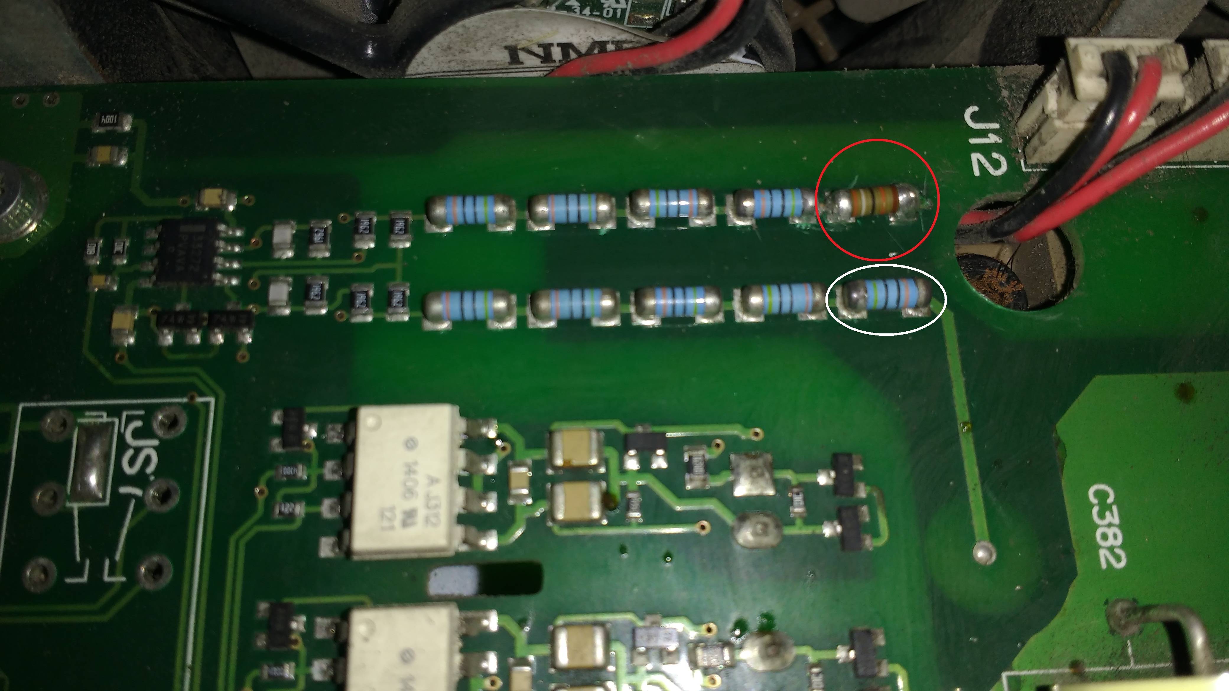
enter image description here

\$\endgroup\$
15
  • \$\begingroup\$ How do you get 400K from those markings? That is a green stripe, right? \$\endgroup\$
    – Finbarr
    Commented Sep 30, 2019 at 13:54
  • \$\begingroup\$ The color seems confusing. I see yellow. In addition, I took out a good resistor and measured it. The meter says 400k. \$\endgroup\$
    – user115094
    Commented Sep 30, 2019 at 13:56
  • 3
    \$\begingroup\$ 10K in 5*400k (2M) is only 0.5%. I would suspect either: whatever caused the first resistor to fail had a similar effect on the second, and/or heat damage while replacing the first made it worse. \$\endgroup\$
    – user16324
    Commented Sep 30, 2019 at 14:00
  • 1
    \$\begingroup\$ You need to pay attention to @BrianDrummond's first comment. If you don't determine why the first resistor failed and remove that fault condition then you will just keep blowing resistors. And when you are replacing resistors in a circuit like this you must also consider their voltage rating and whether they are flameproof. \$\endgroup\$ Commented Sep 30, 2019 at 14:43
  • 1
    \$\begingroup\$ OK that adds to the heat damage hypothesis. I'd replace with 390K and good luck. Any more failures and I'd source 400K parts. \$\endgroup\$
    – user16324
    Commented Sep 30, 2019 at 14:43

1 Answer 1

0
\$\begingroup\$

Do you think the new resistor could have affected the string so that a new resistor got damaged?

I doubt it, the resistor strings look like they're part of different circuits. If the resistor did open, then it was most likely from heat. Each string appears to share the same trace (it looks like in each string the resistors are in series and each string is independent). This means each string has 5 resistors in series. If the resistors are in series and the same value, they should have mostly the same voltage across them and dissipate the same power.

If they died a heat death, then it could have been almost any resistor in the string, if the strings are independent then there is no relation between the death of the resistor circled in white or red.

\$\endgroup\$
4
  • \$\begingroup\$ Surely those components at the left hand side of the chains are linking them together? \$\endgroup\$
    – Finbarr
    Commented Sep 30, 2019 at 15:28
  • \$\begingroup\$ That looks like some kind of filter with two independent channels similar to the circuits below. If I had my guess, they are dropping a high voltage signal down to a more manageable level. Don't know why it would kill the first one though. I think they are independent channles, the circuitry to the left is an isolator and the circuits in between are filters. \$\endgroup\$
    – Voltage Spike
    Commented Sep 30, 2019 at 15:32
  • \$\begingroup\$ Perhaps, but to me it looks more like a differential amplifier based around an MC33272 dual opamp. \$\endgroup\$
    – Finbarr
    Commented Sep 30, 2019 at 15:35
  • \$\begingroup\$ I see that now, you can barely make out the numbers on the IC. It is definitely a MC33272. Maybe some kind of current sensing application? \$\endgroup\$
    – Voltage Spike
    Commented Sep 30, 2019 at 15:44

Your Answer

By clicking “Post Your Answer”, you agree to our terms of service and acknowledge you have read our privacy policy.