1
\$\begingroup\$

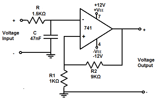
I have this non inverting op-amp circuit:

enter image description here

I would like to calculate the output with the Op-amp noise impact. I can easily find the voltage output, but only if I assume there is no noise.

How to do it with noise Op-amp (assuming others components are "perfect")?

We will use a TI OPA141 Op-amp: http://www.ti.com/lit/ds/symlink/opa141.pdf

Input is signal frequency is 100Hz. I want to use the 6.5nV/sqrt(Hz) but it seems to be a spectral density, and I can't add it to a voltage.

I wanted to use the square of this to find a value in RMS, but it failed and I want a voltage value, not a RMS value. We should have 42.25V^2/Hz

How can I find the noise from the opamp?

\$\endgroup\$
6
  • \$\begingroup\$ There are two things I don't really understand what you're saying. 1) I can't add it to a voltage. But isn't this spec'd by what the datasheet already says to get 6.5nV/√Hz? 2) but it failed and I want a voltage value, not a value. I have no idea what this means. \$\endgroup\$
    – user103380
    Commented Oct 16, 2019 at 18:59
  • \$\begingroup\$ Thanks for your answer. I can't add for example 3V with 6.5nV/√Hz. What is the result of 3V + 6.5nV/√Hz = ? About 2), I edited \$\endgroup\$
    – Tack
    Commented Oct 16, 2019 at 19:08
  • 2
    \$\begingroup\$ You multiply the noise density by the square root of the bandwidth to get the RMS noise output. \$\endgroup\$ Commented Oct 16, 2019 at 19:10
  • \$\begingroup\$ @Kevin White: if my bandwidth is [0Hz, 100Hz], and the output voltage is 5V if there is no noise, so the result will be 5+6.5nV*√100 = 5.000000065V? \$\endgroup\$
    – Tack
    Commented Oct 16, 2019 at 19:19
  • \$\begingroup\$ This is not a linear amplifier. It's a comparator with hysteresis. \$\endgroup\$
    – The Photon
    Commented Oct 16, 2019 at 19:39

2 Answers 2

2
\$\begingroup\$

Input is signal frequency is 100Hz. I want to use the 6.5nV/sqrt(Hz) but it seems to be a spectral density, and I can't add it to a voltage

This is where the bandwidth of the analog system comes in, the max bandwidth determines the noise. Let's say it's an ADC with a low pass filter at 1000Hz. The ADC would see:

(1000Hz)^(1/2)*6.5nV/sqrt(Hz) = 2.05uV-rms

If the total bandwidth is 100Hz then

(100Hz)^(1/2)*6.5nV/sqrt(Hz) = 0.065uV-rms

In addition, the low pass filter on the input only stops noise contribution from the input, the amplifiers bandwidth is not restricted. It is usually best to low pass filter the amplifier for noise purposes.

If you get below the 1uV-rms line for total noise, contributions from resistor white noise starts to become significant and needs to be analyzed.

\$\endgroup\$
3
  • \$\begingroup\$ Thank you for your answer. And how can i convert Vrms to Vdc? \$\endgroup\$
    – Tack
    Commented Oct 16, 2019 at 20:02
  • \$\begingroup\$ referencedesigner.com/rfcal/vrms-to-vpeak-conversion.php \$\endgroup\$
    – Voltage Spike
    Commented Oct 16, 2019 at 20:16
  • \$\begingroup\$ @ tack we convert the RMS to probability; 6.2 sigma is 6.2 rms thus 6.2 * 65uV = 402 uV will be seen for only 1PPM of the time with a duration of 1/system bandwidth (or approximately so) \$\endgroup\$ Commented Oct 17, 2019 at 3:19
0
\$\begingroup\$

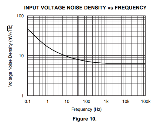
You shouldn't just use some rough noise density number for this calculation. The reference fig for noise in your datasheet is Figure 10.

From the datasheet you linked to: DatasheetNoise

Noise density figures like this show a knee, below which pink low-freq noise dominates the white noise, and above which, white noise. The important parameters are the frequency of the knee (the lower, the better), and the level of the white noise.

You essentially integrate this curve over your bandwidth, and then multiply by your op amp gain to yield rms noise.

Note: This op amp has really bad noise specs.

\$\endgroup\$

Your Answer

By clicking “Post Your Answer”, you agree to our terms of service and acknowledge you have read our privacy policy.

Not the answer you're looking for? Browse other questions tagged or ask your own question.