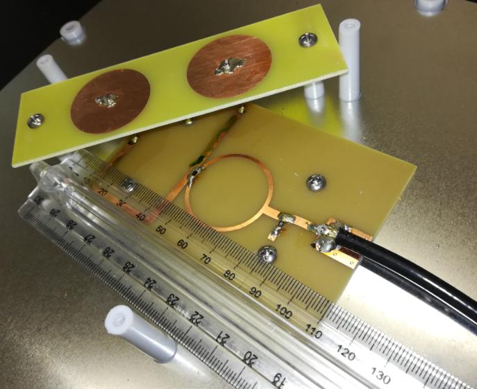
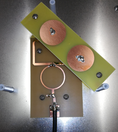
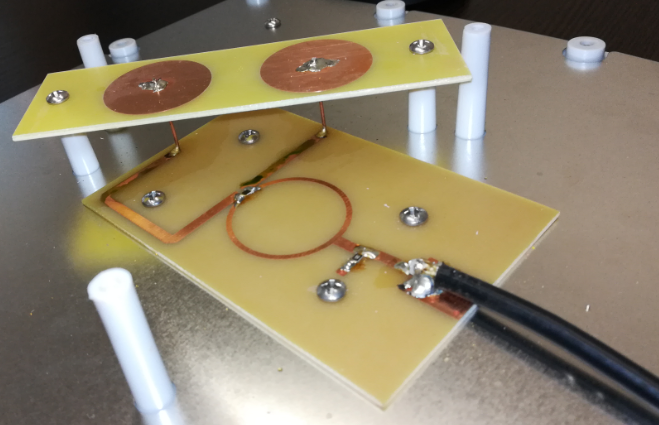
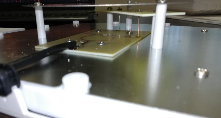
I recently obtained an RHCP antenna, but when I opened it to investigate what's inside of it I found it to be different from the conventional RHCP polarized antenna. I have included pictures in this post, so hopefully, someone can give me an idea of how it operates, such as why is there any antenna above the bottom one?
-
2\$\begingroup\$ simply because the bottom one isn't an antenna. \$\endgroup\$– Marcus MüllerCommented Oct 23, 2019 at 16:35
-
1\$\begingroup\$ also, qualified statements on the workings of that antenna can't be given unless you tell us what the wavelength is in relation to the circular patch radius, the rat-race circumference, and the microstrip "J" length. It might also help to define the main direction of the antenna! \$\endgroup\$– Marcus MüllerCommented Oct 23, 2019 at 16:37
-
\$\begingroup\$ @MarcusMüller Regarding your first comment, out of the two pcb's the one at the bottom looks more like a patch antenna than the top one so I assumed the bottom is the antenna, could you explain why it isnt? On the second comment the frequency is 915MHz which as a wavelength of 0.32m, lenght of the J strip is 3.7cm. Im not sure what you mean by main direction of the antenna. The RF energy is directed orthogonally to the substrate. \$\endgroup\$– JoeyBCommented Oct 23, 2019 at 17:04
-
1\$\begingroup\$ Side note, there appears to be some corrosion on the copper traces. Suggest cleaning with isopropyl alcohol, fine steel wool, alcohol, dry, and coat just the copper with a thin layer of something like polyurethane "clear." If the copper is badly damaged, unit may be scrap. The width (and conductivity) of those traces are critical. \$\endgroup\$– rdtscCommented Oct 23, 2019 at 17:09
-
\$\begingroup\$ @rdtsc looking at the substrate and the 915 MHz: what you say is true, but in this case, things are relatively forgiving. \$\endgroup\$– Marcus MüllerCommented Oct 23, 2019 at 17:18
1 Answer
Let's take this on from the cable:
- The discrete component is probably just something to help with matching the microstrip wave guide on the PCB to the cable impedance. Since that way of soldering the cable to the line certainly isn't the most well-defined one in terms of reliable impedance, that match doesn't need to be overly great.
- The ring-like structure is a balun, which converts between the unbalanced signal from the coax and the balanced signal going into the branches of that "J"
- That J is has different branch lengths, meaning that the right circular patch gets the same signal with an advanced phase compared to what the left patch sees.
- These patches are a bit unusual in their size relative to wavelength, which is why I'm surprised this antenna actually emits nicely normally to the ground plane. Clearly, their phase and shape effects the polarization of the emitted wave, but I fail to see how the circularization works.
EDIT
now after you've added the aluminium disc:
That's the actual antenna; the small patches just act as feeds for the holes in the larger aluminium disk.
So, this is just a helical antenna!
Imagine that you take a helical antenna, and cut it along a plane: That's exactly the plane that the disc lies in. The currents you induce in that disk are just emulating the current distribution that would cause a field identical to that of the helical antenna.
-
\$\begingroup\$ I added two additional pictures, do you know what is the purpose of the silver disc applied above the antenna? Have you come across something like this before or applied it to your designs? \$\endgroup\$– JoeyBCommented Oct 23, 2019 at 18:25
-
2\$\begingroup\$ RF energy isn't transported in electrical circuits; it's transported in E-fields, often between conductors. Think of your coax cable: the wave is transported in the dielectric between inner conductor and shield. So, that disc is very much connected to the copper patches below: there's an E-field between these, and it radiates out from the slots in the disc. \$\endgroup\$ Commented Oct 23, 2019 at 18:32
-
1\$\begingroup\$ @Joey I think slot antennas might fascinate you :) \$\endgroup\$ Commented Oct 23, 2019 at 18:33
-
1\$\begingroup\$ I'd probably actually start with the ARRL antenna book, if that still exists \$\endgroup\$ Commented Oct 24, 2019 at 15:30
-
1\$\begingroup\$ @Joey but if you have access to the CST studio already, you can definitely simulate a lot of entertaining antennas! (CST is expensive, so I'm envious) \$\endgroup\$ Commented Oct 25, 2019 at 8:17

