0
\$\begingroup\$

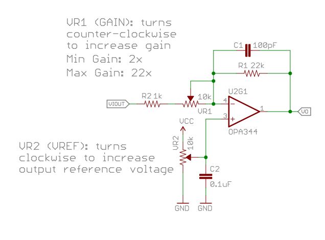
I'm having trouble understanding why the following circuit uses the inverting configuration rather than the non-inverting configuration for amplification.

enter image description here

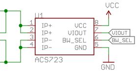
enter image description here

This design is from the Sparkfun Current Sensor Breakout (low-current version): Sparkfun Low Current Sensor Breakout

I do not understand why it can be said that the gain is +2x to +22x. Shouldn't this be -2x to -22x gain since it is an inverting op-amp configuration (A = -R1/R2)?

After doing some reading, the only reasoning I can come up with is the fact that the input impedance of the inverting configurarion is much lower and thus would affect the sensor measurement much less than the non-inverting config.

I do not understand how this inverted output is going directly to an ADC pin in their hookup guide found here: Hookup Guide for Current Sensor Breakout Does the ADC only care about the absolute value?

It is not re-inverted again in firmware either. I think I am missing something extremely trivial and it's bothering me a lot. Also, in my intended application, I would eliminate the trimpot on the positive input of the op-amp and have a direct reference to ground, since I am only interested in sensing positive direct current that my application will consume from a wall adapter.

\$\endgroup\$

1 Answer 1

1
\$\begingroup\$

The hookup guide is mainly for the higher current version, and the code is mainly for adjusting the reference voltage, and not directly meant for taking bidirectional current measurements.

Otherwise you are right, even if the amplifier configuration is inverting, it still can be said to have voltage gain or amplification, and negative gain can be thought as just positive gain with 180 degrees phase shift. The point is, it still amplifies. And the fact is, when current goes upwards, voltage goes downwards - unless you change current polarity to flow into opposite direction to begin with to get upward voltage wih rising current.

The ACS723 datasheet claims it works best when load resistance go ground is above 4k7, but then again the load is not to ground but to reference voltage. There is always the inverting input resistance so it always has load so it is not high impedance.

The measurements are anyway bidirectional, so when you have the gain and reference set up, you can always swap the +ve and -ve current measurement terminals.

But you can't just have op-amp non-inverting input set as 0V reference, because with inverting amplifier, all positive voltages would then cause negative output, and therefore you would need a negative supply voltage for op-amp and for example you could not measure negative voltages with a microcontroller.

As zero current through the bidirectional measurement chip outputs 2.5V, maybe you would like to have 2.5V reference and then choose your gain to be able to measure current both ways. The point is, gain and reference go hand in hand.

\$\endgroup\$

Your Answer

By clicking “Post Your Answer”, you agree to our terms of service and acknowledge you have read our privacy policy.

Not the answer you're looking for? Browse other questions tagged or ask your own question.