2
\$\begingroup\$

I'm working on a design where an RS-485 transceiver IC is connected to a Cat5e cable, hopefully at 96k baud at a distance of up to 150m. I'd like to offer some protection in the design, but I've never really worked with RS-485 or TVS diodes, so I'm looking for some reassurance and advice around the protection implementation.

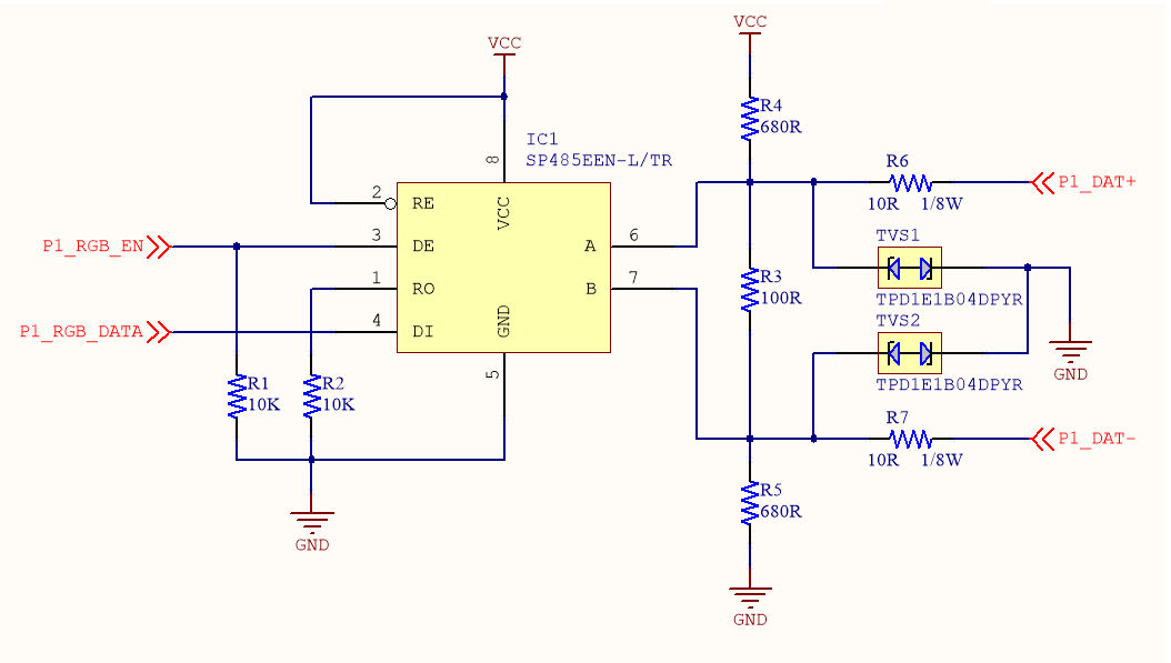
Circuit diagram

I'm using a MaxLinear SP485EEN-L/TR RS-485 transceiver. The TPD1E1B04 TVS diodes have a VBRF of 6.4V and VRWM of ±3.6V.

The data is sent over one of the twisted pairs. Another pin on the RJ45 will provide a ground reference to the other side, and the shield will be grounded.

My thoughts in the design above are as follows:

  • The receiving end will have a matching protection and termination design, the only difference being that IC1 will be configured as a receiver (RE and DE tied to ground, RO outputting data).
  • The termination resistor values (R3, R4, R5) were chosen fairly arbitrarily based on the five or six different conflicting examples I found online.
  • R6 and R7 are intended to offer some minimal current limitation in the case of a short, and act as fuses for high voltage shorts (e.g. short to mains in a catastrophic failure scenario). With 10R on each side, I devalued the usually-specified value of R3 by 20R.
  • R6 and R7 plus the others on the receiving side might help resolve the impedance mismatch between the RS-485 driver (expecting 120R) and the Cat5e cable (which I understand is 100R). Probably won't matter too much at 96k baud though.
  • The positive and negative TLP curves of the TVS diodes show no significant conduction until around 6.3V, which should be sufficient to protect IC1 but shouldn't trigger until there's an actual overvoltage.
  • I wasn't sure whether to leave the RO pin on the SP485 IC floating, since it's unused on this side of the circuit. Same for DI on the receiving side. I couldn't see anything in the datasheet that specified this, or showed what the IO circuitry looked like. I'll likely include pads for resistors on both, but mark them as DNP, unless someone has more info to offer.

Does this design seem sensible? Any major mistakes? Are there any improvements that can be made?

\$\endgroup\$
2
  • \$\begingroup\$ Where does the power come from? And is this a completely isolated device (like a PoE camera), a device at the same ground potential (like in a data centre) or worst case - a separated, independently earthed and powered device (like connecting two PCs in different buildings?) That will determine what protection is required. \$\endgroup\$
    – tomnexus
    Commented Nov 15, 2019 at 4:07
  • \$\begingroup\$ Whoops, I should have clarified the function of this design. The transmitter side is a home automation switch hub, which will be an earthed mains appliance in a rackmount case. The transmitter PCB will be powered using a DC switching supply module, so no mains should ever reach the PCB. The receivers will be button panels powered by +12V delivered over the Cat5e cable, with no earth or separate power feed of their own. The Cat5e cables will be running through walls, so the primary concern is someone shoving a nail through it and a mains feed at the same time. \$\endgroup\$
    – Polynomial
    Commented Nov 15, 2019 at 4:14

1 Answer 1

3
\$\begingroup\$

A real RS485 bus would be setup for bidirectional transmission and not dedicated to one way flow. If you want to use unidirectional flow you should be more apt to study termination techniques for RS422.

Symmetrical parallel termination at each end like you show is what you want for a bus that needs to transmit in both directions.

For unidirectional transmission you really only need the 100 ohm termination at the receiver end. You could also choose 50 ohm resistors in each leg at the transmit side which would be optimal termination for a driver.

The 680 ohm resistors are only needed for fail safe termination at a receiver side to bias the receiver to see a "stop bit" voltage level in case a cable is disconnected. In your case they are not needed at your transmitter driver side.

\$\endgroup\$
11
  • 1
    \$\begingroup\$ I'm still not sure I understand your point about directionality. Is it just a technicality, or are there real design implications that matter for my use-case? Surely it's the just the same as an RS-485 interface whose firmware/software just happens to never send any data in one particular direction? \$\endgroup\$
    – Polynomial
    Commented Nov 15, 2019 at 4:29
  • 1
    \$\begingroup\$ What is so hard to understand. The RS485 spec is for a bidirectional communications bus!! To call what you are doing RS485 is incorrect. For unidirectional transmission you really only need the 100 ohm termination at the receiver end. You could also choose 50 ohm resistors in each leg at the transmit side which would be optimal termination for a driver. \$\endgroup\$ Commented Nov 15, 2019 at 4:37
  • 1
    \$\begingroup\$ Symmetrical parallel termination at each end is what you want for a bus that needs to transmit in both directions. \$\endgroup\$ Commented Nov 15, 2019 at 4:39
  • 1
    \$\begingroup\$ The 680 ohm resistors are only needed for fail safe termination at a receiver side to bias the receiver to see a "stop bit" voltage level in case a cable is disconnected. In your case they are not needed at your transmitter driver side. \$\endgroup\$ Commented Nov 15, 2019 at 4:50
  • 1
    \$\begingroup\$ RS422 is simplex, single V+ supply, Tx= 150mA. RS485 is half-duplex +/-V bipolar Tx=250mA, but both have the same speed*distance limitations of 100kbps*1200m but here only 96kbps *150m is needed. Balanced Impedance is key for CMRR but a single Zo termination is best for one pair vs two R's @ x% tolerance to match cable. Cat5e= 100 Ohms 15% \$\endgroup\$
    – D.A.S.
    Commented Nov 15, 2019 at 17:34

Your Answer

By clicking “Post Your Answer”, you agree to our terms of service and acknowledge you have read our privacy policy.

Not the answer you're looking for? Browse other questions tagged or ask your own question.