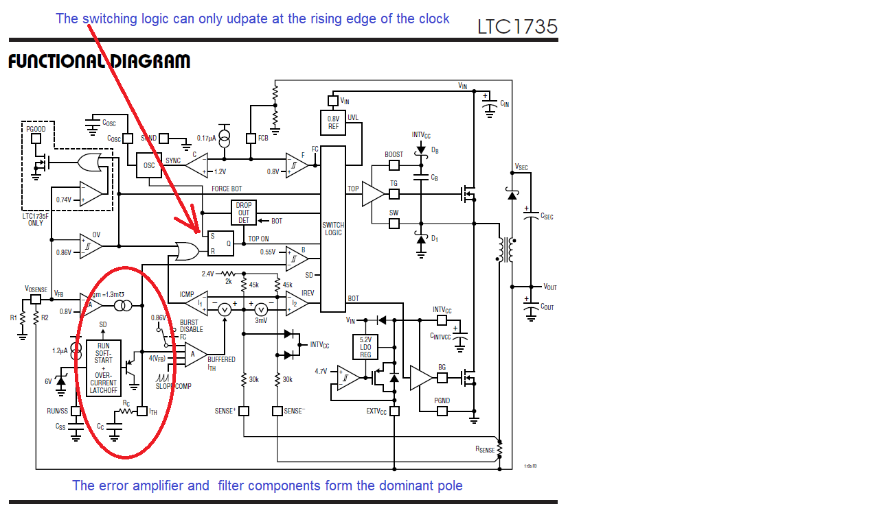
A switch mode supply only updates the output (switch turn on / turn off / duty cycle) once per clock.
As the clock has two edges, but we only update on one of those edges, the maximum output update rate (and therefore bandwidth) is therefore one half of the switching frequency (two updates for a complete cycle requires two control clock cycles).
It is the fact that we update the output based on a clock (not continuously) that makes this a sampled data system.
As noted in the earlier answer, this is not a practical bandwidth for a number of reasons including phase and gain margin. Another issue is switch noise feedthrough (which can be difficult to remove).
A more typical loop crossover frequency is 1/5 of the switching frequency or lower.
A sampled data system is one in which the data are sampled at discrete intervals, rather than being continuous.
One continuous system is an analog filter (made up of linear components and perhaps amplifiers) and therefore the output represents the input as modified by the circuit at all times (ignoring the time it takes for the signal to pass through the filter).
In a sampled data system we only know what the input is at a set of given instants in time and we do not know what the input is between those points (this is why we filter the input so only a known band of frequencies is actually present at the input such as at the input to an ADC).
A switch mode power supply is analogous to an ADC in that the output (from the feedback loop) is measured only at specific points in time and therefore we ensure that the filtering limits the bandwidth of that signal.
There are internal components that help form the filter so here is the illustration from the LTC1735 (a high performance SMPS controller although a little old); the details of the analog parts of the loop are documented in AN76.

There are external components here (which is helpful as they form part of the overall loop).
Even though the filters the error amplifier and the output filter (from the output capacitor) are analog, the decision of what to do can only be taken at the rising edge of the clock regardless of what happened between those clocks.
As we want to get the best overall response, we limit the loop bandwidth so that the samples are taken much faster than the loop can actually change (the same as we do with any ADC).
As with any ADC, there is a nyquist limit of < Fsample / 2 but that is still a relatively high frequency; to get the best overall response we trade off some of that potential loop frequency response for better loop information (the sample rate is much higher than the bandwidth of the sampled signal).
So a sampled data system is one (such as an ADC) only measures the actual input at discrete points in time rather than continuously.

