beginner here, searching for some guidance as I set up my first multiplexer.
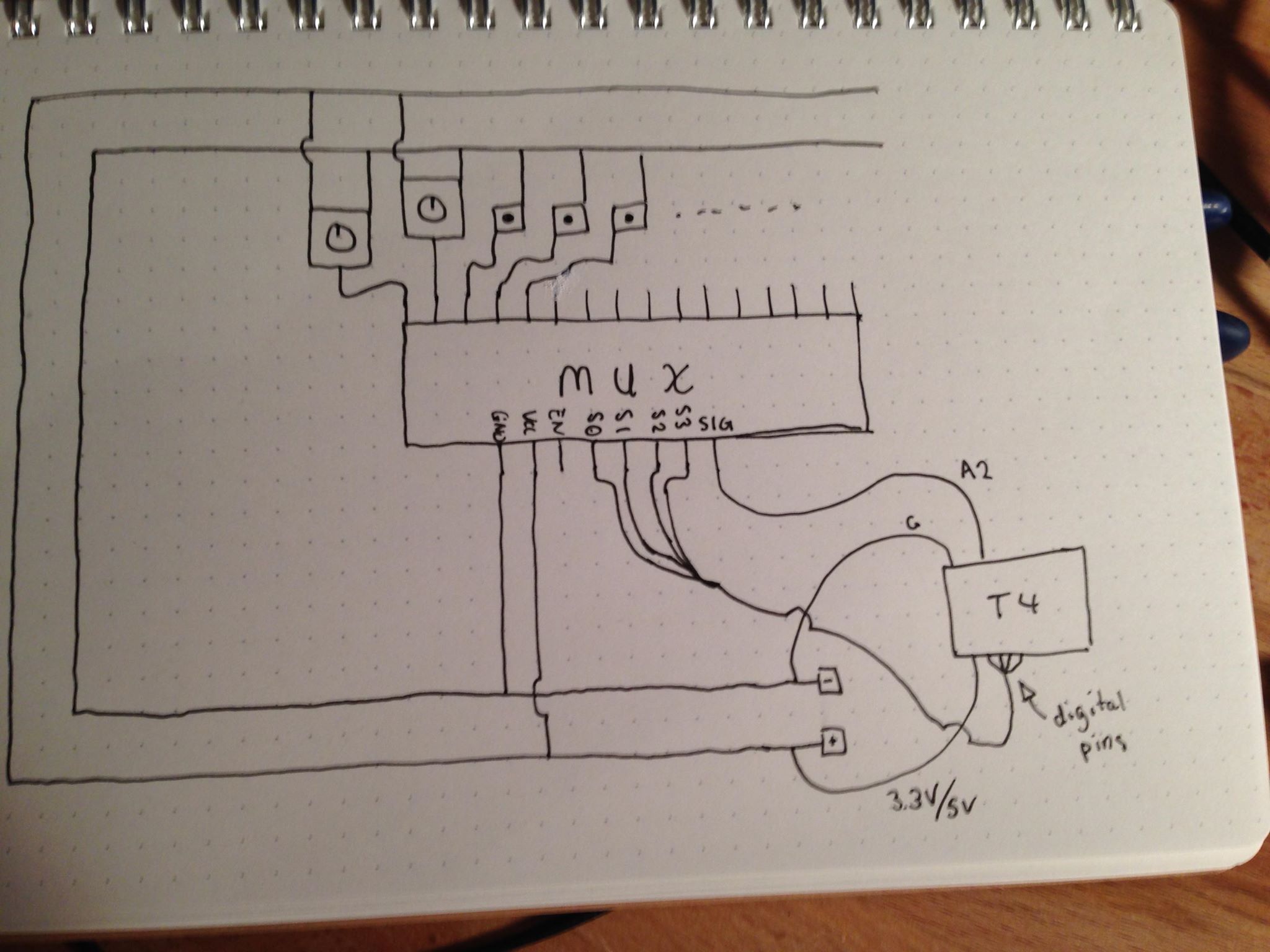
My breadboard was wired as follows:
 The T4 refers to my Teensy4.0 microcontroller, its hooked up to the breadboard ground and I have tried using both the 3.3V and 5V power pins hooked up to the red line on the breadboard and had identical results between either. The signal pins of the mux are routed to my digital pins on my T4 and the signal is hooked up to an analog pin on the board. The larger components in my diagram are potentiometers and the smaller ones are tactile buttons.
With this wiring hookup, adjusting the first potentiometer from the left appears to change the signal reading for most of the other input channels. Pressing the first button from the left also was effecting the readings on channels 8-11, and one of the buttons was effecting the readings of a channel nowhere near it.
Obviously I'm doing something wrong here, but the first thing that confuses me is that before attempting this wiring with the multiplexer, I was attaching the knobs and buttons directly to the input pins on my T4 which worked no problem. Why was the wiring ok without a multiplexer but stopped working when it was added? A friend of mine noted that my wiring wouldn't work because the buttons were just floating, but it worked fine when directly hooked up to the digital input pin.
When I looked online to see how other people were wiring multiplexers for their projects, it appeared as though they were doing the same thing I did in this diagram, with the exception of adding a resistor between the current and the knob/button. Will this solve my problem? What value resistors should I be using?
If anyone could help me design a wiring setup that will work for me I'd really appreciate it!! I'm scrambling to finish an overly ambitious Christmas gift that has had a lot gone wrong and I'm in the final stretch!!

EN, is that intended and you know that you can leave it floating? Also you need a pull up resistor at each channel you use to read a button state. Your code could also be of interest, how fast are you switching channels? \$\endgroup\$