0
\$\begingroup\$

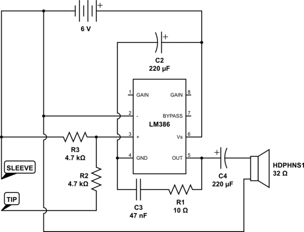
I tried to make an audio amp based on LM386 but the output is noisy when the audio is playing. Here is my circuit schematic I built on a solderless protoboard:
schematic

simulate this circuit – Schematic created using CircuitLab

Power is supplied from four 1.5V batteries. I also added 50pF between input terminals to filter-out radio noise. When there is no sound playing, the amp is nice and quiet, but once the music starts the noise appears. There is also some reverberation when the music stops. When the inverting input is connected to the ground the effects get even worse. My guess is that there is a feedback loop between output and input, but I don't know why and how can be fixed. Adding coupling capacitor and/or voltage divider at non-inverting input or adding a bypass 10uF capacitor doesn't change anything.

EDIT:
According to the comments, I removed the 50pF capacitor between the inputs, connected the inverting input to the ground and added the voltage divider at the input. This made the sound much cleaner, but there was no gain. Output volume was not amplified regardless of the capacitor between pins 1 and 8. Adding DC coupling before the potential divider makes gain work again but also makes the output really noisy.

\$\endgroup\$
9
  • 1
    \$\begingroup\$ Breadboards encourage longer wire-paths - a short-path PCB might be more successful. The many connections to pin 4 (GND) can cause problems. Does C2 have a long wire path? Try moving it direct from pin 6 to pin 4 at the chip with short leads. \$\endgroup\$
    – glen_geek
    Commented Dec 28, 2019 at 14:59
  • 2
    \$\begingroup\$ Your problem is you didn't follow the datasheet. Pins 2 and 3 are not correct, for a start. \$\endgroup\$
    – JRE
    Commented Dec 28, 2019 at 15:00
  • 1
    \$\begingroup\$ and as @JRE states, this makes the question too broad to answer: If you're not doing everying in the datasheet, there could be a plethora of bad things happening. Since the LM386 is a multi-source component, the actual "out of specifications" properties between the LM386 you have and someone else might have aren't necessarily even the same. So, build a datasheet-compliant circuit first, then come back! \$\endgroup\$ Commented Dec 28, 2019 at 16:48
  • \$\begingroup\$ Reverberation needs some storage. This circuit doesn't have it. Have you already tested with another amp if the problems are already in your signal that you feed to your amp? As well you can try another signal source which is tested already elsewhere and seen to have perfect signal. \$\endgroup\$
    – user136077
    Commented Dec 28, 2019 at 16:48
  • 1
    \$\begingroup\$ Do you have an oscilloscope? My experience with the LM386 is that it likes to oscillate at quite high frequencies at a specific point in the audio waveform, and that this oscillation is worse when it's on a breadboard. Getting some O-scope pictures would help us diagnose your specific problem. (And note, there are better parts around -- that thing has been around since the 1970's!) \$\endgroup\$
    – TimWescott
    Commented Dec 28, 2019 at 16:50

2 Answers 2

4
\$\begingroup\$

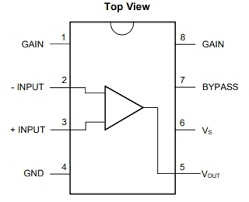
The LM386 has two inputs; they are differential like so: -

enter image description here

Ignoring the ridiculous value of the input capacitor on pin 2 in your picture, you basically have both inputs fed from the same signal and that won't work very well at all. Use one of the standard circuits is my advice and watch out for power 0V currents flowing through input areas. A standard circuit: -

enter image description here

\$\endgroup\$
2
  • \$\begingroup\$ Having 50pF capacitor between + and - doesn't make them receive the same signal because the chip has internal 50k pull-down resistors, so only signal above 400kHz will go through this cap. Otherwise, it will behave as an open circuit. \$\endgroup\$
    – warownia1
    Commented Dec 28, 2019 at 20:31
  • \$\begingroup\$ I don’t believe for 1 minute that anyone who has read the data sheet (even badly) would have installed a capacitor of value 50 pF. \$\endgroup\$
    – Andy aka
    Commented Dec 28, 2019 at 21:05
4
\$\begingroup\$

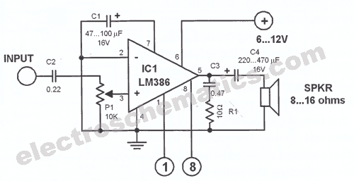
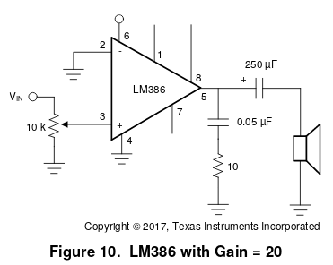
The simplest way to fix your circuit is to build it as the datasheet recommends:

enter image description here

Notice the variable resistor connected to pin 3. You describe the problem as "noise when the music is playing," which makes me think what you actually have is distortion.

The most common sources of audio will have a line level output (PC) or a headphone output (smart phone, mp3 player, etc.) Signals at those levels amplified by a factor of 20 (as your circuit would do) will cause clipping (extreme distortion) in the audio.

The fix is to lower the volume. That's what that 10k variable resistor is there for. It reduces the signal level so that the output to the speaker doesn't clip.

Next after that is to add a series capacitor between \$V_{IN}\$ and your music source. A 1µF non-polarized capacitor would be fine. That should take care of any DC offset that may be causing problems.


Those two steps should fix your problems. The LM386 generally works well if you follow the notes in the datasheet. It isn't a great amplifier, but hasn't survived all these years by being a complete piece of crap.

\$\endgroup\$
3
  • \$\begingroup\$ It's not necessarily the audio clipping, because the distortion/noise was most audible when the music was quiet rather than loud. Adding the voltage divider made the signal clean but at the same time gain stopped working (I suppose it disturbed the internal voltage offsets). Adding DC coupling at the input fixed the gain, but the noise came back. \$\endgroup\$
    – warownia1
    Commented Dec 28, 2019 at 20:37
  • \$\begingroup\$ Can you describe the "noise?" \$\endgroup\$
    – JRE
    Commented Dec 28, 2019 at 20:42
  • \$\begingroup\$ It reminds me of a sound that blowing or wind makes (it goes away when I add a low pass filter at the input). The noise is not there when no music is playing which makes me suspect that it's some kind of feedback. Also, when the music stops playing, the sound persists for a brief moment. \$\endgroup\$
    – warownia1
    Commented Dec 28, 2019 at 20:54

Your Answer

By clicking “Post Your Answer”, you agree to our terms of service and acknowledge you have read our privacy policy.

Not the answer you're looking for? Browse other questions tagged or ask your own question.