I have a fuel dispenser, which has one keypad and two displays, each display has three of 7 segment LCDs.
I want to control the fuel dispenser with a PC or a phone. The way to do this in my knowledge is by attaching Raspberry to the fuel dispenser; program the raspberry pi so that it can imitate the same work as the keypad; and read what is written on the display so that I can insert it in a database as a record. Then I can communicate with the pi in different ways.
Now the imitation of the keypad was very easy and I have no problems with it. The problem I am facing is that I am still not able to read what is written on the display.
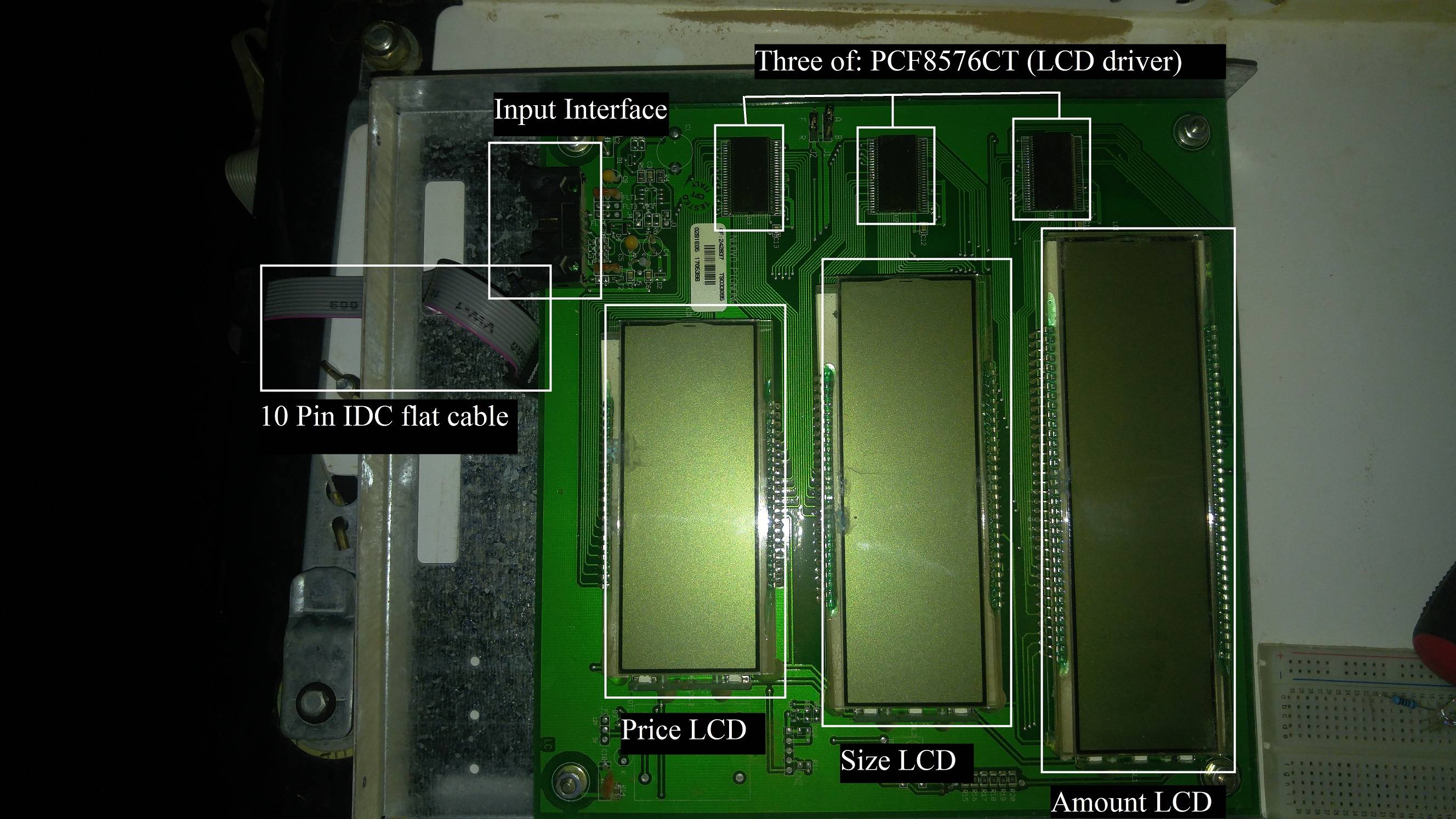
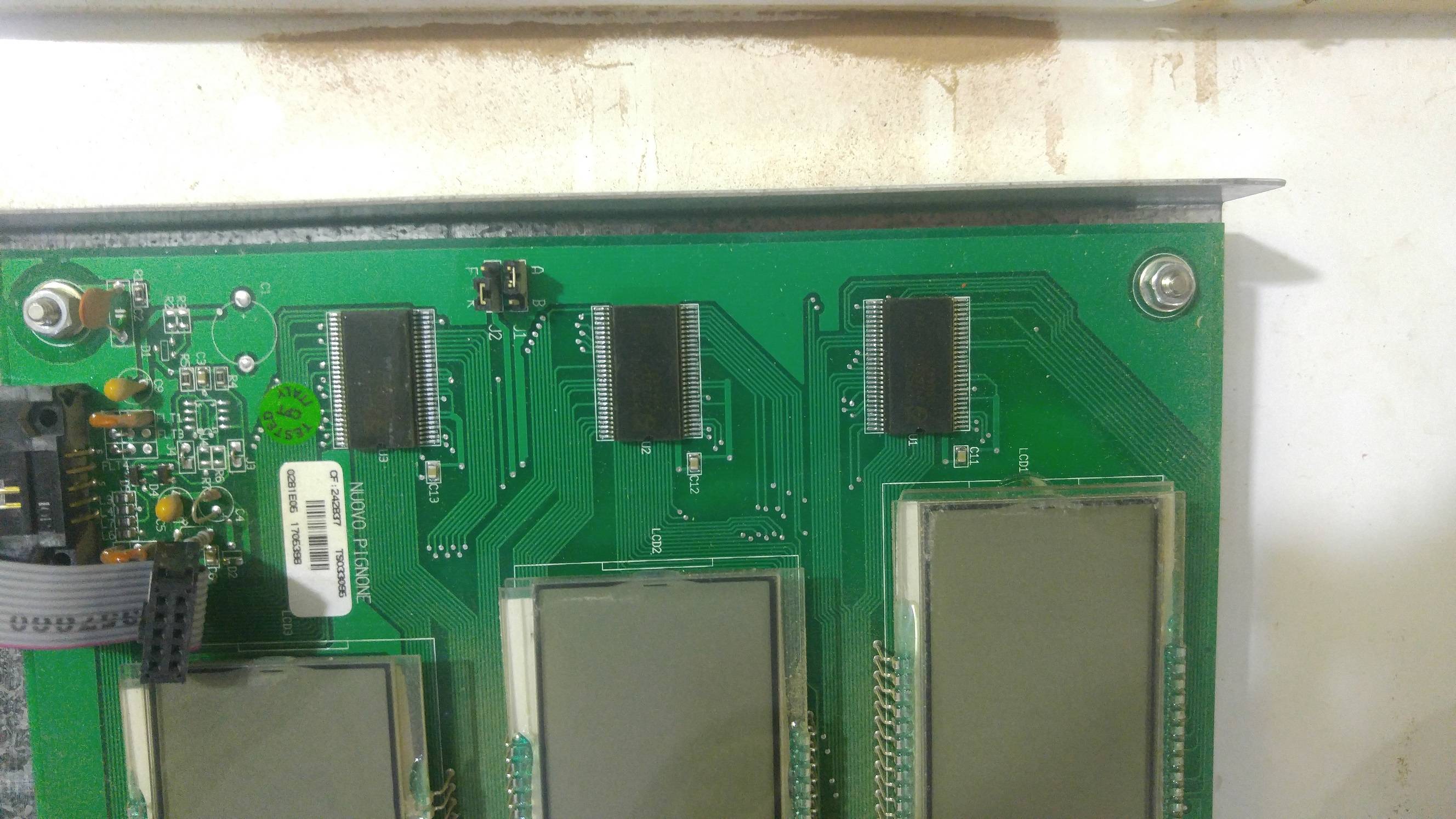
Let me first show you what does the display looks like:
Now the kaypad has 12 buttons ( from 0 to 9, an A button, and F button).
. If I click on A (which means I want to insert maximum amount): the size LCD shows nothing and the amount LCD shows one "0".
. If I click on F (which means I want to insert maximum capacity): the size LCD shows one "0" and the amount LCD shows nothing.
. If I just start pumping fuel with typing nothing, the display starts showing the calculations on the size LCD and its equivalent amount on the amount LCD.
Now data comes from the motherboard, which is sealed to the display through the 10 Pin IDC cable. After measuring each pin of the cable I found:
. 2 Pins of ground
. 2 Pins of 12V
. 1 Pin of 5V
. 2 Pins of 3V
. 3 Pins of -0.3V
So I started to look for which pin sends data. I used Raspberry pi 3B+, and I attached the ground of the raspberry pi to the ground of the cable, and the serial RX of the raspberry pi to each of the other pins (I used 1k Ohms resistor in between).
I found that:
. 2 Pins of 12V and 1 Pin of 5V has nothing
. 1 Pin of 3V sends data each 1 seconds (It also sends data when I click on the keypad)
. 1 Pin of 3V send data each 2 seconds or maybe 3 seconds (when I click on the keypad, it sometimes sends data and sometimes it doesn't)
. The other 3 Pins of -0.3V send only zeros (Even if I click on the keypad)
Now the problem is that I don't understand the data that I receive from the raspberry pi. I just see it as random numbers.
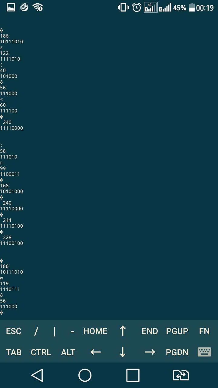
Here is what I see from one Pin of 3V:

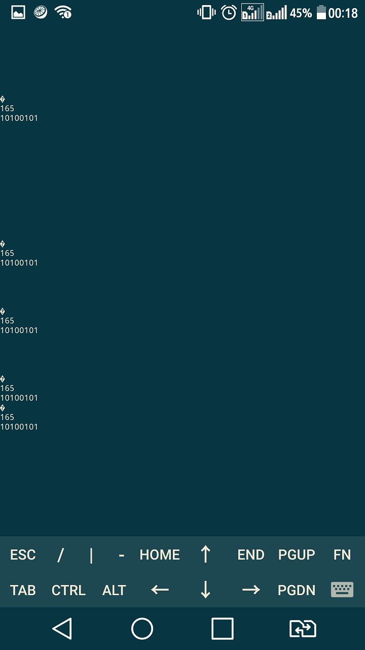
This is from the other 3V Pin:

It even changes it value other than 165 sometimes.
This is the python code I am using on Raspberry pi:
import serial

ser = serial.Serial("/dev/ttyS0", baudrate=9600, bytesize=8, timeout=1)

try:
      while 1:
            response = ser.read()

            if response:
                  print response
                  print ord(response)
                  print bin(ord(response))[2:]
                  print "---------------------"
            #line = ser.readline()
            #if line:
            #     print line
except KeyboardInterrupt:
      ser.close()
I tried changing baudrate and bytesize, and received the same random numbers.
Here you can find the datasheet of the "PCF8576CT" LCD driver:
https://www.nxp.com/docs/en/data-sheet/PCF8576C.pdf
I apologize for making this long, and I hope you can find solution to this.
Thank you


