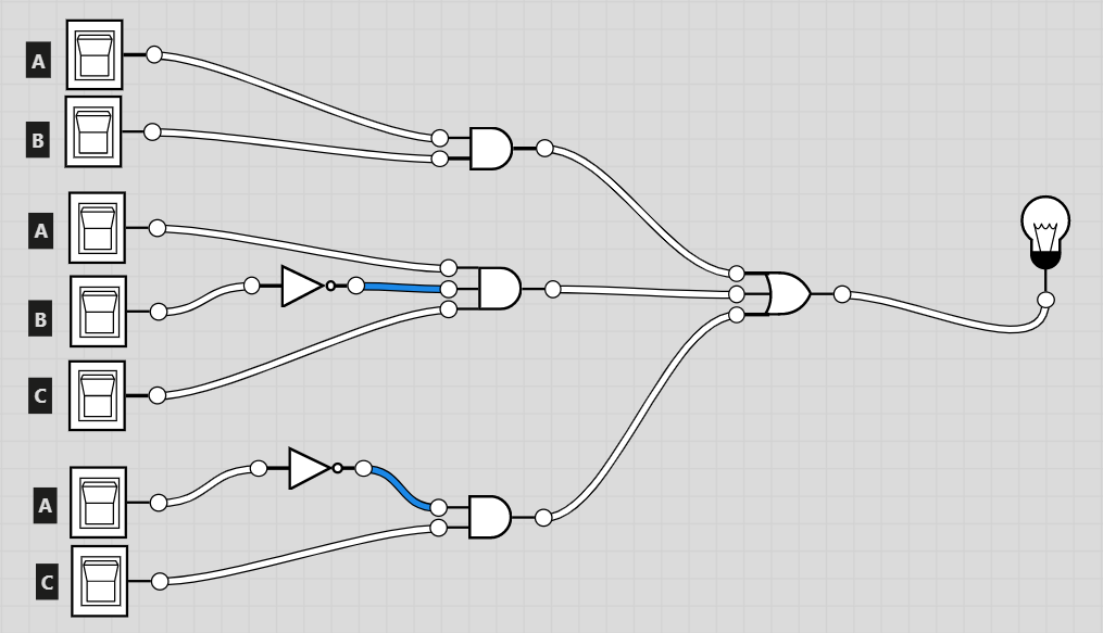
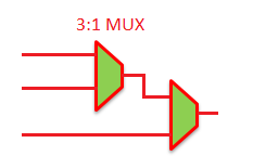
Recall the definition of a multiplexer: it's a device with several inputs and one output. Specifically, it has n binary selection inputs (usually denoted as \$S_0\$ through \$S_{n-1}\$) to select between 2n data inputs (usually denoted \$D_i\$). The selected data input is passed through to a single output.
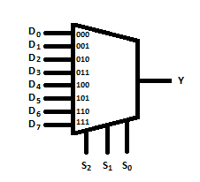
Your multiplexer circuit symbols are missing the selection inputs. For example, a three-input, eight-output multiplexer is usually drawn like this:

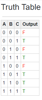
The simplest way to use a multiplexer to implement a logic circuit is to map, one-to-one, the truth table's values to each of the mux data inputs. In other words, the data inputs will either be 0 or 1 (or electrically, HIGH or LOW) and the selection lines will be controlled by your logic inputs.
For extra credit, you can think about how you could use some logic signals as data inputs, which may allow you to reduce the size of your multiplexer. For example, I notice that when \$A\$ is zero, the output equals \$C\$. With a bit of thought you might be able to see how to extend this concept, and produce your same truth table with just a 4-to-1 mux.


