0
\$\begingroup\$

I am trying to drive 4 parallel TEC elements. (TEC1-12706) I intend to run them together up to 12A (or 3A each.)

I am using an ATMega328p (in the form of an Arduino Uno Board) to control the system, but it's only means of variable output is a low frequency PWM. Do to their nature, TEC elements are unsuited to PWM. The efficiency is inversely proportional to the square of the current. In addition, apparently they wear out quickly if voltage swings too much, so a relatively smooth DC voltage is required. (Probably around around 1%, or 0.12V)

I found this similar question, and it appears a buck-converter could work for this purpose, however... My required current is higher and the control frequency is lower, which seems to result in the need for impractically large components.

Something like this: (The resistors represent the 4 TEC Elements)
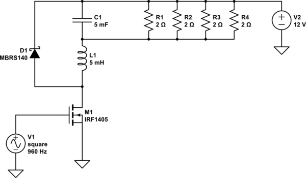
schematic

simulate this circuit – Schematic created using CircuitLab

Ignoring the MOSFET and diode currents for a moment, I am more worried about L1 and C1, since those seem ridiculously large.

My question is: What can I do to avoid needing such high rated components, other than increasing control frequency? Alternatively, is there another approach that might work better? Possibly an RC filter to form a DAC, and then use a power op-amp?

I am thinking there must be some way to add additional stages, or maybe attach multiple of these converters in parallel, but I'm not sure exactly how to do that. If I understand correctly, adding capacitors in parralel increases both capacitance and max allowed ripple current, totals sum together. However, for inductors, they apparently loose inductance in parallel, but still gain max safe current, as the load is distributed. Seems like a catch-22.

Any help (or even just advice) is appreciated!

\$\endgroup\$
5
  • \$\begingroup\$ The false spec is the low frequency, increase 100k to 2M \$\endgroup\$
    – D.A.S.
    Commented Jan 2, 2020 at 22:35
  • \$\begingroup\$ I would, but the micro I am using can only PWM at 490Hz or 960Hz, without changing registers. (Which may have unintended consequences.) Apparently it can go as high as 62kHz, but you start loosing resolution above that. I don't know what that would do to it's ability to use I2C, etc, but this definitely seems like it's worth looking into. Possibly even using another micro. \$\endgroup\$
    – Meta
    Commented Jan 2, 2020 at 22:48
  • \$\begingroup\$ You can get faster PWM by sacrificing resolution. Apparently the Atmega328 can output up to 8 MHz PWM with 1 bit resolution (and probably an external clock). Of course a 1 bit PWM is not very useful for most purposes, but if you can get 2 MHz with 4 bit resolution, maybe that will be sufficient for you? withinspecifications.30ohm.com/2014/02/20/Fast-PWM-on-AtMega328 \$\endgroup\$
    – Dampmaskin
    Commented Jan 2, 2020 at 23:48
  • \$\begingroup\$ @Dampmaskin Yeah, that seems like the best bet! Even if it screws up I2C (can't remember if it relies on the timer or not), I could at the very least use a second 328, and use parallel IO to send it commands. Certainly beats being stuck at 960Hz! \$\endgroup\$
    – Meta
    Commented Jan 3, 2020 at 1:39
  • \$\begingroup\$ If you're going to add a dedicated IC for PWM, you might as well look into specialized parts. Google high frequency pwm controller. \$\endgroup\$
    – Dampmaskin
    Commented Jan 3, 2020 at 8:00

2 Answers 2

1
\$\begingroup\$

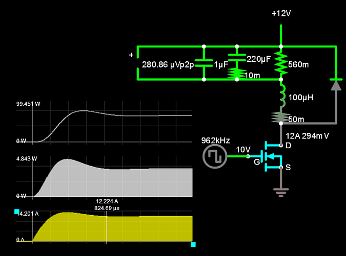
The turn on overshoot without feedback depends on how much losses you allow in the FET (RdsOn) as L/R ratio affects Q or inverse damping factor.

enter image description here

Simulation with 4 sliders

\$\endgroup\$
4
  • \$\begingroup\$ That is one heck of a lot smaller inductor! Although the switching frequency is 100x more than what my chip will do... I really wish I could go to 962kHz, but even if I use a better micro, I still can't make PCB's, so I'm using proto-board. And everybody says you can't do high frequency switching without very carefully designed PCB layouts. Is there a chance this could still work? With the 328P I believe I would have 4 bit resolution at 1Mhz, but I have actually not messed with the timer registers yet. \$\endgroup\$
    – Meta
    Commented Jan 2, 2020 at 23:49
  • \$\begingroup\$ you can adjust it down to any frequency and see the rise in ripple. I made a slider from 50k ~1M \$\endgroup\$
    – D.A.S.
    Commented Jan 2, 2020 at 23:50
  • \$\begingroup\$ I see them now, I did not realize it was interactive at first. Definitely seems to perform! I think I can get the pwm up 1Mhz. My biggest remaining concern is the fact that I am using perfboard (should have mentioned that!), and common advice that says perfboard can't be used for high-frequency switching. Is this likely to be an issue in this frequency range? \$\endgroup\$
    – Meta
    Commented Jan 3, 2020 at 2:24
  • \$\begingroup\$ yes it will be an issue with wire inductance \$\endgroup\$
    – D.A.S.
    Commented Jan 3, 2020 at 3:17
0
\$\begingroup\$

Build a conventional high frequency buck converter using a modern ic controller and small inductors and capacitors. Control the output of the converter with a dc voltage that you generate with the arduino, ( with filtered p. w. m. as is usually done with an arduino. ) The cost of an ic and the few parts around it is much less than the cost of a large inductor and low esr capacitor you would need at low frequencies.

\$\endgroup\$
2
  • \$\begingroup\$ How exactly does one "control the output of the converter"? Is it possible to make the controller IC try to match a voltage level you supply? I thought they operated based on a fixed ratio of the supply voltage. (Sorry, I don't know what to expect from them because I have never actually used one before!) \$\endgroup\$
    – Meta
    Commented Jan 2, 2020 at 23:22
  • \$\begingroup\$ Yes, usually converter circuits compare some fraction of the output voltage to a reference in order to maintain regulation. You probably want to modify the circuit either to control the fraction circuit( a digital potentiometer?) or to create the “reference” voltage with your arduino instead of the chips’s reference. If you are just trying to do this once, maybe you could find some Chinese circuit board buck regulator that is controllable, and you won’t have to design your own. \$\endgroup\$
    – user69795
    Commented Jan 4, 2020 at 0:24

Your Answer

By clicking “Post Your Answer”, you agree to our terms of service and acknowledge you have read our privacy policy.

Not the answer you're looking for? Browse other questions tagged or ask your own question.