0
\$\begingroup\$

I'm creating a water level indicator so I can turn on a pump when the water level gets too low. I have NPN transistors, but I would like the transistor to act as a switch that closes when the water level drops below a certain height. The NPN transistor I used for the experiment seems to do the opposite (close the switch when the water level is high enough), so I figured I need to use a PNP transistor instead. However, after following this SO suggestion and flipping the connection to the battery terminal as well as the LED, the LED did not turn on as expected when the water level gets too low. I would appreciate your advice.

The circuit below lit the LED when the water level closed the circuit. How do I get the LED to turn on when the circuit is open?
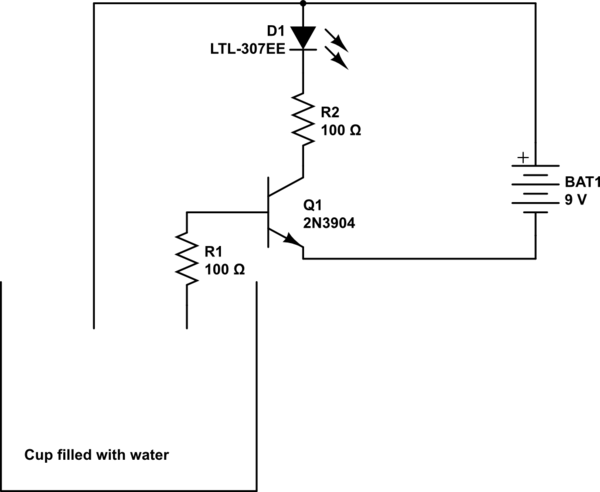
schematic

simulate this circuit – Schematic created using CircuitLab

\$\endgroup\$
1
  • 1
    \$\begingroup\$ The water could be >> MOhms and fail. Do you not have any specs? \$\endgroup\$
    – D.A.S.
    Commented Jan 4, 2020 at 0:25

1 Answer 1

3
\$\begingroup\$

schematic

simulate this circuit – Schematic created using CircuitLab
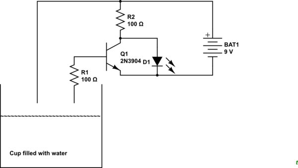
Figure 1. Modified schematic. LED is on when probe is dry.

Move the LED as shown in Figure 1.

  • When the probes are dry Q1 is off and the LED is lit via R2.
  • When the probes are wet Q1 is on and shorts out the LED.

The disadvantage with this simple fix is that current is wasted when the LED is off.

Your 100 Ω resistor value is a bit low (but is also the CircuitLab default). For an LED with a 2 V forward voltage you will drop 7 V across R2. A 1 kΩ resistor will limit the current to 7 mA which will be quite bright on a modern LED.

\$\endgroup\$
5
  • \$\begingroup\$ I really like the little water 'waves' in the cup. \$\endgroup\$
    – Oldfart
    Commented Jan 4, 2020 at 0:07
  • \$\begingroup\$ This better be salt water to get Water <10k to drive 100 Ohms < 2V or 80mA on collector. \$\endgroup\$
    – D.A.S.
    Commented Jan 4, 2020 at 0:29
  • \$\begingroup\$ OP said that the original circuit was working. \$\endgroup\$
    – Transistor
    Commented Jan 4, 2020 at 3:07
  • \$\begingroup\$ @Transistor Not economical use of batteries. It may be better in the original circuit to create an offset on the base with a resistor and connect the electrodes between the base and the emitter \$\endgroup\$
    – AltAir
    Commented Jan 4, 2020 at 6:38
  • \$\begingroup\$ Thanks! Your circuit works if I increase the resistor connected to the diode to 680 ohms \$\endgroup\$
    – st4rgut
    Commented Jan 4, 2020 at 23:35

Your Answer

By clicking “Post Your Answer”, you agree to our terms of service and acknowledge you have read our privacy policy.

Not the answer you're looking for? Browse other questions tagged or ask your own question.