1
\$\begingroup\$

I am trying to create an updated version of a mems mic board, like this one from sparkfun. They use an INMP401 mems mic (which is not recommended for new designs) and an OPA344 for the preamp stage (20 years old, from the datasheet creation date).

My objective is to improve it a bit in terms of a wider frequency response, better noise tolerance, low power, etc. using a different mic and a different opamp. By "different" I mean more recent.

I have been checking some application notes on the topic, like this one from AnalogDevices and this one from ST.

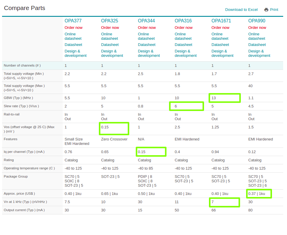
In the end, I have some parts that I am comparing but couldn't decide which one to select. The only feature for the OPA344 that is better than the others is its low power consumption, but for Slew Rate, Noise, THD, and Bandwidth, all are better than it. Here is the comparison table: (green boxes are what I think are pros of each part).

enter image description here

Is there any tip about which additional feature I should look at when designing a preamp stage? Any suggestions from the previous list? In case low power is not a requirement, which opamp could be selected instead?

Thanks.

\$\endgroup\$
4
  • 1
    \$\begingroup\$ My objective is to improve it My objective when answering questions is to understand the objectives and this doesn't tell me anything. \$\endgroup\$
    – Andy aka
    Commented Jan 28, 2020 at 12:03
  • \$\begingroup\$ For your information, INMP401 is not recommended for new designs as there are better mics in terms of SNR, THD, frequency range etc... Also, there are more OpAmp aside to OPA344, with better specs in noise, slew rate, power, price, etc. Given that OPA344 is an old part (still useful, though) I wonder if a more recent part could replace it. \$\endgroup\$ Commented Jan 28, 2020 at 12:15
  • \$\begingroup\$ When replacing a part in a circuit, comparing technical specs is the wrong 1st approach - you should constrain your requirements to what the actual circuit delivers (and what improvements in performance you want from your improved circuit). Only then should you make comparisons like the one above. maybe you have done this already and, if you have you should make your question more accessible (and less likely to waste other folks time) by stating those important requirements. \$\endgroup\$
    – Andy aka
    Commented Jan 28, 2020 at 12:23
  • 1
    \$\begingroup\$ For audio, offset and bandwidth kind of seem irrelevant since audio is AC and device bandwidth is typically orders of magnitude higher than 20kHz and your mic probably can't even go half that high. \$\endgroup\$
    – DKNguyen
    Commented Jan 28, 2020 at 14:12

1 Answer 1

2
\$\begingroup\$

I believe your chart choices are correct: the OPA344 was chosen for its low quiescent current, making it a good choice for battery-powered applications. The trade-off comes from your other desired areas of improvement.

The OPA344 has a gain-bandwidth product of only 1 MHz, which makes it a poor choice for high-frequency amplification in your circuit. In your circuit, an ideal op-amp's closed-loop DC gain from the resistors would be 100K/1.5K or about 67, and from your gain-bandwidth product of 1 MHz, your op-amp's open-loop gain is 67 at 15KHz (often considered the high end for audio). The closed-loop gain is obviously lower. The addition of a 100 pf capacitor in the feedback loop further decreases the high-frequency gain but keeps the op-amp stable with the phase shift to be experienced at high frequency at this high gain. So this circuit will be fine for lower frequency audio, but the high frequencies will be attenuated.

Increasing the op-amp's speed will allow you to keep the gain and have better high-end response, at a cost of op-amp power. As in all designs, the trade-offs are what makes it fun.

One other caveat, when using op-amps in audio circuits, beware of claims of "rail-to-rail." If you dig through the data sheet, you will almost always find that an op-amp will not be able to deliver the same current near the rail; this can cause distortion with higher-amplitude signals.

Good luck!

\$\endgroup\$
1
  • \$\begingroup\$ Thanks for your advice! \$\endgroup\$ Commented Feb 5, 2020 at 9:41

Your Answer

By clicking “Post Your Answer”, you agree to our terms of service and acknowledge you have read our privacy policy.

Not the answer you're looking for? Browse other questions tagged or ask your own question.