0
\$\begingroup\$

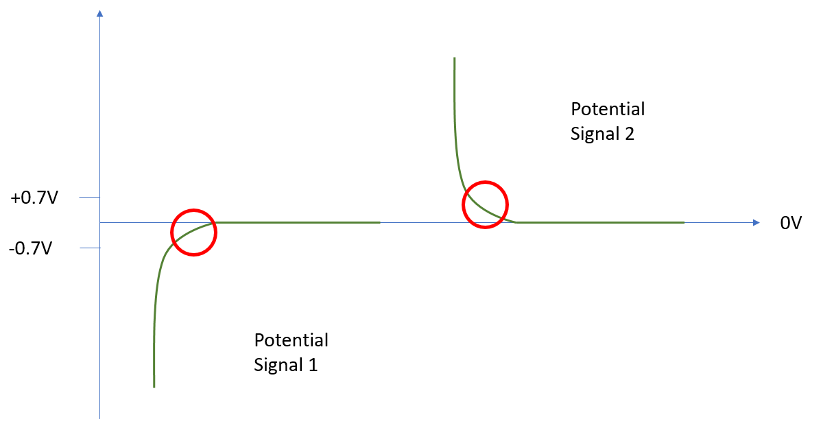
I'm working on an application which requires me to read a curve on an analogue signal. Depending on external influence the curve could either be a negative voltage or positive voltage. The shape of the curve doesn't change so it's effectively a direct inversion. The ADC of the STM32F4 that I am using has a Vref- that must be tied to Vss ie. ground (vref+ is currently 3V3 but I'm planning to reduce that when I get around to it). The ADC is currently configured to 12bits @ 1Msps. I'm taking 30 samples for each time i get a signal at the indicated point.

enter image description here

My problem: I can read Potential Signal 2 fine, it is within my ADC reference voltage. I cannot read Potential Signal 1 as it is outside my ADC reference voltage.

Solutions: I was initially just going to add a DC offset of 0.7V or so with a 5V rail that I have but ripple which may be present on the supply (LM78L05) could affect my reading as I am currently converting with an approximate accuracy of 800uV per bit.

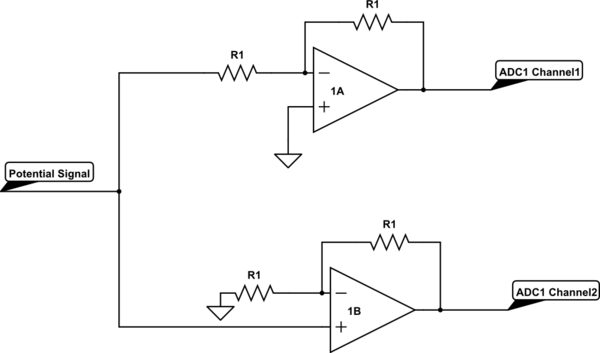
I've also considered configuring the ADC to use two channels. One channel would be connected to the signal via a low gain inverter (this would flip potential signal 1 and amplify it a little) and channel 2 would be connected to the signal via a low gain non-inverting amplifier. I'm thinking that I could do this with a 2 Op Amp package and with precision resistors for the feedback loop.
schematic

simulate this circuit – Schematic created using CircuitLab

I could then use software to determine which of the two possible signals is the correct one (eg. potential signal 1 would mostly read a zero in ADC channel 2 but would look correctly inverted on ADC channel 1).

Does this make any sense, is there a simpler way to do this? My biggest issue is that my accuracy needs to be quite high, in the region of 100s of microvolts. Would voltage ripple present on the supply for the op Amp affect the output?

Idea number 2 inspired by @Rohat Kılıç's answer:
schematic

simulate this circuit

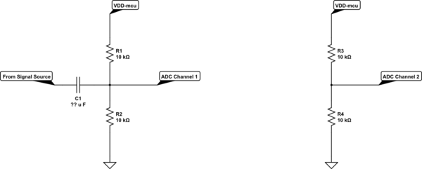
As I was initially concerned about adding an offset because of the potential added noise/ripple from the power rail, could I stick with the idea of using 2 channels of the ADC, add the same offset to both with the signal only being present on channel 1 and then channel1 - channel2 to remove the common noise?

thanks for the help

\$\endgroup\$
3
  • \$\begingroup\$ Your "non-inverting amplifier" is not going to work, check the circuit diagram for that again. You created a positive feedback. \$\endgroup\$
    – jusaca
    Commented Jan 30, 2020 at 12:56
  • \$\begingroup\$ I flipped terminals on 1B without thinking about what I was doing. I've edited the schematic, but the question is more about the best way to read the signal. \$\endgroup\$
    – ChrisD91
    Commented Jan 30, 2020 at 13:13
  • 1
    \$\begingroup\$ You could use an inverting amplifier with a reference providing a DC offset - that would invert the sense of the signal but that is easy to correct in software. I usually choose a reference that is mid-span for the ADC. Precision references are very inexpensive. \$\endgroup\$ Commented Jan 30, 2020 at 13:24

2 Answers 2

1
\$\begingroup\$

I wouldn't choose this tack, because the negative-going signal would not be within the range of allowable input signals on your microcontroller. Note that for the STM32f405 the absolute minimum input for a 5V tolerant pin is \$V_{SS} -0.3\$.

The way this is done is to offset the input signal to be midrange for zero input, attenuating if necessary.

Note in your circuit, the inverting gain is -1 and the noninverting gain is +2.

I see your need for accuracy, but suggest that if you can't handle a factor of two that attenuation would give you, you should be looking at your signal chain, perhaps considering a higher bit A2D.

An alternate method would be to use a precision rectifier to make the signal positive, and a comparator, read on a digitial input, to tell you if the signal is positive or negative. This might be more disturbing to your signal chain than the offset and attenuation.

\$\endgroup\$
3
  • \$\begingroup\$ The simplest way to me seemed to be to just add a small DC offset from the 5V rail with a voltage divider but I was concerned about any ripple/noise present on the voltage rail as my measurements are sensitive. I've updated my question to include a possible way around this using two channels of the ADC both having the same offset. \$\endgroup\$
    – ChrisD91
    Commented Jan 30, 2020 at 14:23
  • \$\begingroup\$ Any ripple or noise on your rail will probably impact your measurement in similar ways regardless of approach, @ChristopherDyer -- You're strategy should be to get rid of that ripple. \$\endgroup\$ Commented Jan 30, 2020 at 14:29
  • \$\begingroup\$ The negative-going signal doesn't reach his MCU, only op-amp outputs reach the MCU. And those are clipped to the op-amp power rails. \$\endgroup\$
    – Ben Voigt
    Commented Mar 4, 2022 at 19:24
1
\$\begingroup\$

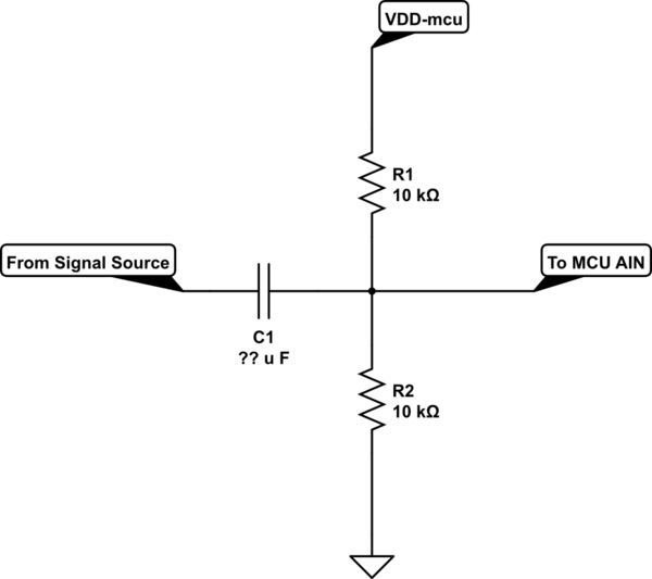
You can offset the signal.

schematic

simulate this circuit – Schematic created using CircuitLab

The output of the circuit above is the input signal having an offset of VDD/2. I didn't show an exact value for C1 (coupling or DC blocking capacitor) because it depends on the frequency of the signal. Note that C1 and parallel combination of R1 and R2 form a hi-pass filter having a cut-off frequency of \$f_C = 1 / (\pi R C)\$ where \$R=R1/2=R2/2\$.

\$\endgroup\$
3
  • \$\begingroup\$ I did consider a simple offset like this but thought that any disturbance/ripple on the VDD rail would manifest itself on to the signal \$\endgroup\$
    – ChrisD91
    Commented Jan 30, 2020 at 13:53
  • \$\begingroup\$ This AC-couples the input, which may or may not be acceptable. \$\endgroup\$ Commented Jan 30, 2020 at 14:28
  • \$\begingroup\$ @ChristopherDyer if you use VDD directly as Vref then, even if you don't add a DC offset, the measurements will still be affected by any ripple/disturbances on VDD line. If you can get rid of the ripple then adding an offset will not be a problem. \$\endgroup\$ Commented Jan 30, 2020 at 15:23

Your Answer

By clicking “Post Your Answer”, you agree to our terms of service and acknowledge you have read our privacy policy.

Not the answer you're looking for? Browse other questions tagged or ask your own question.