0
\$\begingroup\$

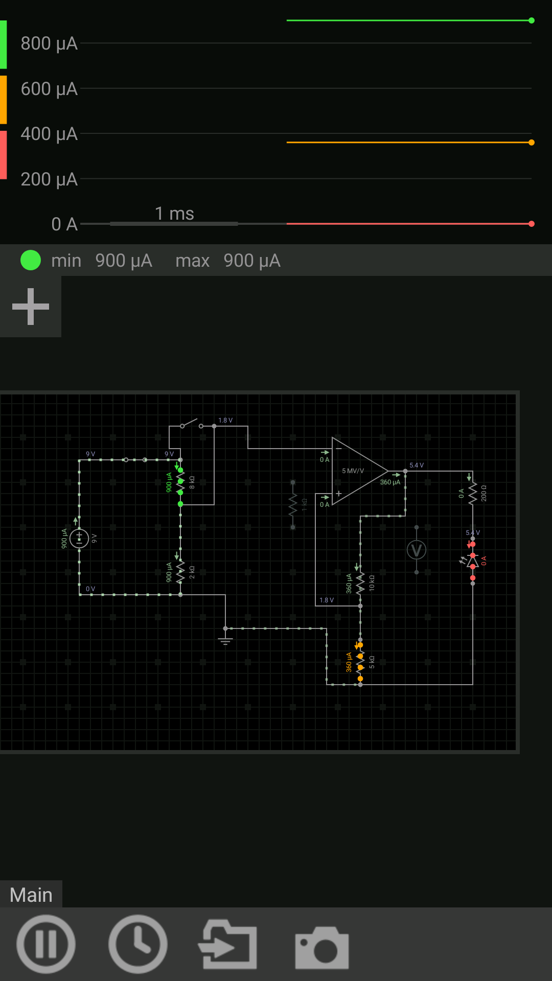
I am working on a project which needs a Schmitt trigger. I designed it using IC UA741. I am using a single power supply of 9V. I am grounding the V-.
enter image description here

Here is my design.

The circuit works perfectly in this software as well as other software.

When I do the same in hardware it is not working. I was even getting 2V at V- pin i.e 4 pin. Even though I had grounded it. And the output voltage is always 5.67 V at pin 6.

Can Anyone help me and highlight my fault?

Thank you

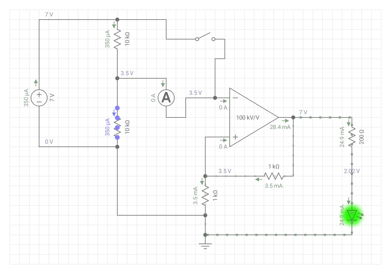
Edit... This is my new circuit. Is there any visible erors here? I haven't tried it on hardware yet. enter image description here
Thank you

\$\endgroup\$
8
  • 2
    \$\begingroup\$ If you have grounded pin 4, but measure 2 volts there, it is not grounded - check your wiring. The schematic shows the LED the wrong way up. \$\endgroup\$ Commented Feb 4, 2020 at 2:44
  • \$\begingroup\$ Led is fine....It's was just for testing.... \$\endgroup\$ Commented Feb 4, 2020 at 2:49
  • \$\begingroup\$ I will test the wiring.Thank you \$\endgroup\$ Commented Feb 4, 2020 at 2:50
  • 3
    \$\begingroup\$ The voltage levels you are using will not work with a 741 (or even an LM358). You need to pay attention to details such as the common mode range of the opamp. \$\endgroup\$ Commented Feb 4, 2020 at 3:13
  • \$\begingroup\$ Look down the list of reasons not to use a 741 and you will see at least one reason right at the top. \$\endgroup\$
    – Andy aka
    Commented Feb 4, 2020 at 8:11

1 Answer 1

1
\$\begingroup\$

Few thoughts. Check your connection to ground as peter Bennett mentioned.

Second Issue is that your op-amp cant run close to the ground rail as Kevin White mentioned. Look up common mode input range. Your input is running at 1.8 V where as you can only go down to about 3V on the inputs according to the data sheet assuming a +-15v supply it can go +- 12 (VICR "Common mode input range"). It will behave similarly at 9 Volts. This effectively leaves your operating area on the inputs between 3V and 6V on this op-amp. Where as you are running the op-amp at 1.8 volts on the input.

If this is the problem, the solution would be to find an op-amp that can go down to 1.8 volts and lower on the inputs or to change your dividers. Where 8k and 2k resistors changed to 5k on the Vin-. And the 10K going to 1k and 5k going to 9k on Vin+. This would let the operating voltage of the input be 4.5 with an output of 5V.

\$\endgroup\$
2
  • \$\begingroup\$ Thanks I didn't knew about common input range.I will try it in hardware then. \$\endgroup\$ Commented Feb 4, 2020 at 12:03
  • \$\begingroup\$ yes it is an annoying factor to consider. I would recommend getting a different op-amp that runs closer to the rails as you are using 9 volts which is much different from the +- 15 volts this was designed for. \$\endgroup\$ Commented Feb 4, 2020 at 21:25

Your Answer

By clicking “Post Your Answer”, you agree to our terms of service and acknowledge you have read our privacy policy.

Not the answer you're looking for? Browse other questions tagged or ask your own question.