0
\$\begingroup\$

Preamble: I have little knowledge of electronics in detail, but I know how to solder, have a working brain and am fearless :)

There are many low-cost Microwave Radar Switch PCBs out there (very popular is the RCWL-0516). I just came across the rather unknown XZG-LDK-6: The neat feature of this board is that it works on the power it is switching (as long as it is between 3.3 and 12 volts). In other words: It simply sits between the PSU and whatever device (lamp, motor etc.) you intend to power.

In my case I want to power (5v USB) a wall-mounted Android tablet, which I use as Smarthome controller. The idea is that the tablet is sleeping/in screen-saving mode, but immediately wakes up (= shows the control panel) as motion gets detected: disconnecting the USB power from the tablet for a moment does the job.

The catch is that I need the Microwave Radar Switch to operate in reverse mode: When motion gets detected it should NOT close the circuit, but open it. So constant power to the tablet with no motion, no power with motion detection. As if one would unplug and replug the USB plug on the tablet.

Unfortunately I can't find a schematic of the XZG-LDK-6 on the web and it seems impossible to figure out the manufacturer (there are trading companies on Alibaba and AliExpress, but no manufacturer).

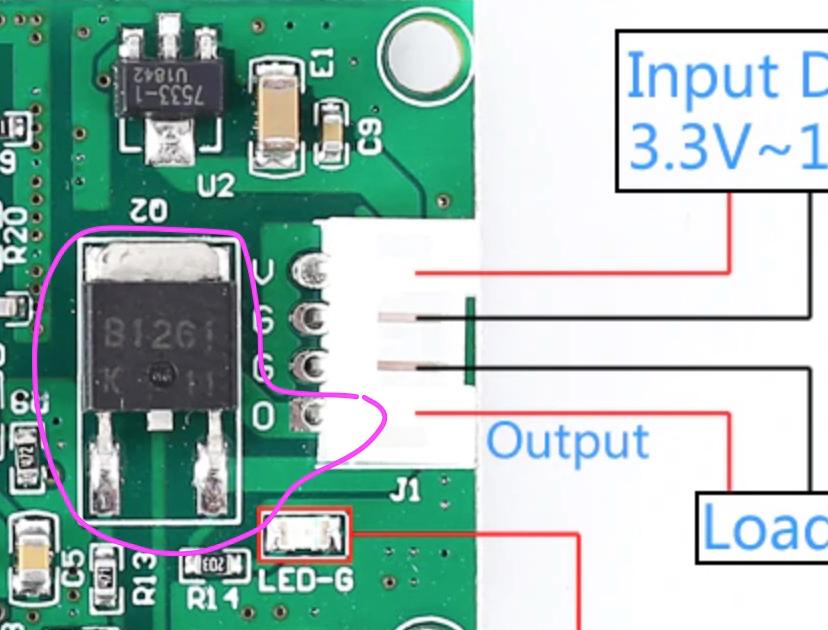
When looking closely, one can see that the B1261 transistor (Q2) seems to be directly providing the output power.

My question is: How to revert the NO (normal open) to NC (normal closed) behavior? With a relay this would be easy, but how do I do this with this transistor? Are there NC and NO types of transistors? Do I simply rewire the existing B1261 transistor?

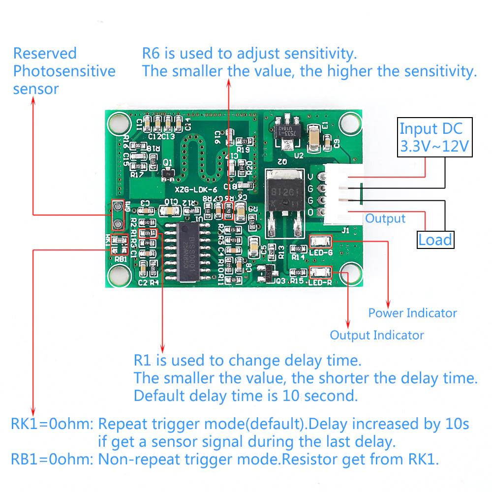
enter image description here

enter image description here

\$\endgroup\$
7
  • \$\begingroup\$ All transistor switches are inverting. \$\endgroup\$
    – D.A.S.
    Commented Feb 4, 2020 at 21:59
  • \$\begingroup\$ Any reason you can't just operate a relay which has normally-closed contacts? \$\endgroup\$ Commented Feb 4, 2020 at 23:29
  • \$\begingroup\$ @BruceAbbott Two reasons: 1. I need/want to avoid the clicking a relay would do. 2. Height. The switch sits right behind the tablet on the wall. \$\endgroup\$
    – Dr. Woo
    Commented Feb 5, 2020 at 1:05
  • \$\begingroup\$ @TonyStewartSunnyskyguyEE75 Which means in my case, that I have to do exactly what!? \$\endgroup\$
    – Dr. Woo
    Commented Feb 5, 2020 at 1:08
  • \$\begingroup\$ Add another switch of suitable size to invert NO to NC \$\endgroup\$
    – D.A.S.
    Commented Feb 5, 2020 at 1:09

1 Answer 1

1
\$\begingroup\$

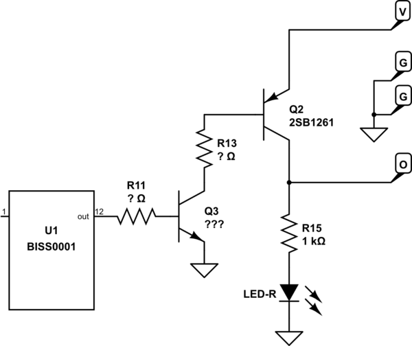
I traced the output section of your RADAR module from the product photo. It appears to look like this:-

schematic

simulate this circuit – Schematic created using CircuitLab

The BISS0001 is designed for use in PIR motion detectors, and performs a similar function in the RADAR detector. When a signal is detected pin 12 goes high, turning on Q3 through R11. This then connects R13 to ground, drawing current out of Q2's Base to turn it on. As each transistor inverts the signal it comes out on module pin 'O' in the same phase as the IC output, ie. Q2 pulls up when the RADAR detector output is high.

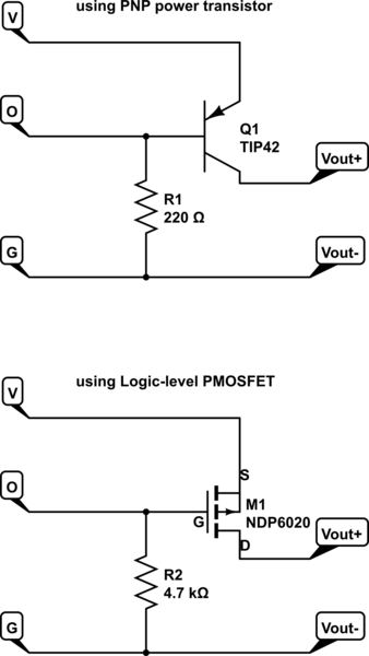
To make the output pull up when the RADAR output is off you need an extra stage of inversion. The easiest way to do this is add another PNP bipolar transistor or P-Channel MOSFET, with a pull-down resistor to ensure that it gets sufficient bias when turned on. When the module output is on it shorts across the Base-Emitter or Gate-Source junction to make the transistor turn off.

The additional circuit would look like this:-

schematic

simulate this circuit

In the PNP bipolar version the pull-down resistor has to supply enough current to keep the transistor fully turned on ('saturated') at maximum output current. Most of the time the resistor will have 5V across it, so it will dissipate significant power (~110 mW for 220 Ω, so a 1/4 watt or higher rated resistor should be used).

The MOSFET version is more efficient because a FET is turned on by voltage, so the pull-down resistor just has to draw enough current to charge the Gate-Source capacitance quickly and soak up any EMI or leakage current. However finding a suitable P-Channel FET may be more difficult. It should have RDSON < 0.1 Ω at 4.5 V.

\$\endgroup\$
1
  • \$\begingroup\$ Awesome! I'll give your MOSFET solution a try as soon as the Radar Switches from China show up. Thanks a lot! \$\endgroup\$
    – Dr. Woo
    Commented Feb 5, 2020 at 18:35

Your Answer

By clicking “Post Your Answer”, you agree to our terms of service and acknowledge you have read our privacy policy.

Not the answer you're looking for? Browse other questions tagged or ask your own question.