29
\$\begingroup\$

We have been begun studying diodes in electronics 1 and I have really basic question that may be really dumb but I cannot find an answer online.

If a diode is in series with a resistor and a voltage source that is set at the exact forward voltage drop value of the diode, what will be the voltage drop across the resistor? It can’t be zero but I’m guessing it must be close.

We have learned that normally you would subtract the forward voltage (0.7 V) from the loop but this circumstance doesn’t make sense to me.

\$\endgroup\$
4
  • 1
    \$\begingroup\$ There is a Shockley diode equation. With it these solutions work out fine. Are you interested in it? \$\endgroup\$
    – jonk
    Commented Feb 9, 2020 at 6:33
  • \$\begingroup\$ What is the current?? \$\endgroup\$
    – Hot Licks
    Commented Feb 9, 2020 at 13:32
  • 4
    \$\begingroup\$ Simple answer: There is no "exact forward drop voltage" i.e. the diode does not suddenly turn on and start conducting at that exact voltage, but has a more gradual slope, around that voltage. \$\endgroup\$ Commented Feb 10, 2020 at 18:56
  • \$\begingroup\$ It depends on the model you are expected to be using. Given electronics 1, you are probably expected to be using the Ideal Diode Model. Is this true? If not, what diode model have you been taught? Usually you will be expected to answer using whatever level of model has been taught in class. As your classes become more advanced, so do the models - and the answers (such as jonk's elaborate explanation). Or are you looking for a real-world answer to go along with the ideal models you've been taught? \$\endgroup\$
    – J...
    Commented Feb 11, 2020 at 20:07

7 Answers 7

35
\$\begingroup\$

Sample Schematic

So please find for your entertainment, analysis of the following circuit:

schematic

simulate this circuit – Schematic created using CircuitLab

(Most of the material that follows here can be readily found at this Wikipedia site: diode modeling. I will, however, take a different approach to their closed solution answer.)

Shockley Diode Equation

Assuming operation at its calibration temperature, the only relevant equation for the LED is the Shockley diode equation:

$$I_\text{D}=I_\text{SAT}\left(e^{\frac{V_\text{D}}{\eta\, V_T}}-1\right)$$

That equation is readily re-worked to solve for \$V_\text{D}\$:

$$V_\text{D}=\eta\, V_T\,\operatorname{ln}\left(\frac{I_\text{D}}{I_\text{SAT}}+1\right)$$

So, we have two different perspectives on the diode/LED.

For a diode-connected small-signal BJT, it is usually the case that the emission co-efficient (aka non-ideality factor) is \$\eta=1\$. But for many discrete diodes such as the 1N4148 or 1N4007, \$\eta>1\$. (It won't be less than 1.) Some LEDs will have rather high values (exceeding 4. not infrequently.)

The saturation current, \$I_\text{SAT}\$, is best seen as an extrapolated \$y\$-axis intercept. I talk about it here and also here and here.

\$V_T=\frac{k\, T}{q}\$ is the statistical thermal voltage and is a basic physics parameter with many important uses. At room temperature, it's often taken to be \$\approx 26\:\text{mV}\$.

Mathematical Closed Solution

The KVL equation for the above circuit is:

$$\begin{align*} V_\text{CC} - R\,I_\text{D} - V_\text{D} &= 0\:\text{V}\\\\ V_\text{CC} - R\,I_\text{D} - \eta\;V_T \, \ln{\left(\frac{I_\text{D}}{I_\text{SAT}}\right)} &= 0\:\text{V} \end{align*}$$

The problem here is in solving for \$I_\text{D}\$. You can easily solve this in an iterative fashion. Or, if you have a piece of paper with the diode equation plotted, you can use a ruler to add the resistor "load line" and find an approximate intercept. But for a closed mathematical solution without iteration, you need the product-log function (aka the LambertW function):

$$\begin{align*} V_\text{CC} - R\,I_\text{D} - \eta\;V_T \, \ln{\left(\frac{I_\text{D}}{I_\text{SAT}}\right)} &= 0\:\text{V}\\\\ \frac{V_\text{CC}}{\eta\,V_T} - \frac{R\,I_\text{D}}{\eta\,V_T} &= \ln{\left(\frac{I_\text{D}}{I_\text{SAT}}\right)}\\\\ e^{^{\frac{V_\text{CC}}{\eta\,V_T}-\frac{R\,I_\text{D}}{\eta\;V_T}}} &= \frac{I_\text{D}}{I_\text{SAT}}\\\\ 1 &= \frac{I_\text{D}}{I_\text{SAT}}\cdot e^{^{\frac{R\,I_\text{D}}{\eta\,V_T}-\frac{V_\text{CC}}{\eta\,V_T}}}\\\\ e^{^{\frac{V_\text{CC}}{\eta\,V_T}}} &= \frac{I_\text{D}}{I_\text{SAT}}\cdot e^{^{\frac{R\,I_\text{D}}{\eta\,V_T}}}\\\\ \frac{R\,I_\text{SAT}}{\eta\,V_T}\cdot e^{^{\frac{V_\text{CC}}{\eta\,V_T}}} &= \frac{R\,I_\text{D}}{\eta\,V_T}\cdot e^{^{\frac{R\,I_\text{D}}{\eta\,V_T}}}\\\\ &\text{set }u=\frac{R\,I_\text{D}}{\eta\,V_T}\\\\&\therefore\\\\ u\,e^u&=\frac{R\,I_\text{SAT}}{\eta\,V_T}\cdot e^{^{\frac{V_\text{CC}}{\eta\,V_T}}}\\\\ u&=\operatorname{LambertW}\left(\frac{R\,I_\text{SAT}}{\eta\,V_T}\cdot e^{^{\frac{V_\text{CC}}{\eta\,V_T}}}\right)\\\\ \frac{R\,I_\text{D}}{\eta\,V_T}&=\operatorname{LambertW}\left(\frac{R\,I_\text{SAT}}{\eta\,V_T}\cdot e^{^{\frac{V_\text{CC}}{\eta\,V_T}}}\right)\\\\ I_\text{D}&=\frac{\eta\,V_T}{R}\cdot\operatorname{LambertW}\left(\frac{R\,I_\text{SAT}}{\eta\,V_T}\cdot e^{^{\frac{V_\text{CC}}{\eta\,V_T}}}\right) \end{align*}$$

(For those interested in more details about the product-log function, aka LambertW, please see Wolfram's LambertW site.)

Now, suppose \$V_\text{CC}=9\:\text{V}\$ and \$R=220\:\Omega\$. For the LED, let's use parameters taken from a Luminus PT-121-B LED: \$\eta=8.37\$, and \$I_\text{SAT}=435.2\:\text{nA}\$. (Assume \$V_T\approx 26\:\text{mV}\$, of course.) Then we'd find \$I_\text{D}\approx 29.9\:\text{mA}\$ and \$V_\text{D}\approx 2.42\:\text{V}\$. This is very close to the Spice simulation for the device and circumstances.

Or suppose we use the parameters for the 1N4148, \$\eta=1.752\$, and \$I_\text{SAT}=2.53\:\text{nA}\$, and use \$V_\text{CC}=5\:\text{V}\$ and \$R=1\:\text{k}\Omega\$. Then, for this common diode, we'd find \$I_\text{D}\approx 4.34\:\text{mA}\$ and \$V_\text{D}\approx 654\:\text{mV}\$.

As you can see, this works for all diode types. (The main limitation is the fact that \$I_\text{SAT}\$ varies widely over temperature -- discussed towards the end of the discussion on 'simplified diode models' where its variations due to one of the most important results from statistical mechanics, the Boltzmann factor, are further discussed.)

Summary

Closed solutions for basic diode questions are never basic. However, for most purposes it's usually enough to make a few simplifying assumptions and be "close enough for all intents and purposes." (To read about some of these, see 'simplified diode models' already mentioned a moment ago.) So you probably will never really need to do the above work. It's just nice to know what's involved, should you wonder about it. (Mostly, so you'll realize just why you use those simplifying assumptions, instead.)

Also take note that the closed solution is a large-scale solution and solves the question over a very, very large range of circumstances.

You were wondering about what happens when the applied voltage is equal to the diode voltage. But, in reality, the diode voltage adjusts itself to the circumstances. It's not fixed. So if you try to apply the so-called "diode voltage" to the circuit, the diode will instead adjust its voltage still lower so that the resistor's voltage drop will be "just enough" to provide the current that is "just enough" to yield the needed diode voltage to make up the difference. That's the real answer here. The above mathematical solution is just a complicated way of saying the same thing, but quantitatively instead of in a "hand-waving" way.

All of the above applies exactly the same as for any forward-biased diode of any kind. Even those with substantial (in the application) Ohmic lead resistance (which is then just added to the series resistance for analysis.)

\$\endgroup\$
14
  • 7
    \$\begingroup\$ I appreciate this wording: "the diode will instead adjust its voltage ... just enough". \$\endgroup\$ Commented Feb 10, 2020 at 6:11
  • 6
    \$\begingroup\$ @pericynthion All the same parameters and logic still apply. The LED is just a segue. Not an error. \$\endgroup\$
    – jonk
    Commented Feb 10, 2020 at 8:59
  • 3
    \$\begingroup\$ @pericynthion In fact, I mentioned regular dude types earlier in the text. Nothing changes in the analysis, at all. \$\endgroup\$
    – jonk
    Commented Feb 10, 2020 at 9:05
  • 7
    \$\begingroup\$ This is my favorite answer on the whole electronics stack-exchange site by far. Short, to the point, and so deep that everyone who reads it learns something. \$\endgroup\$
    – user55924
    Commented Feb 10, 2020 at 9:15
  • 6
    \$\begingroup\$ @user55924 Thanks for the kind words and I'm glad you can see the depth and breath. However, this is merely my parroting of the incredible work of a few very smart people long before me. Some appreciate it, some never will (to their own loss.) \$\endgroup\$
    – jonk
    Commented Feb 10, 2020 at 9:31
20
\$\begingroup\$

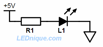
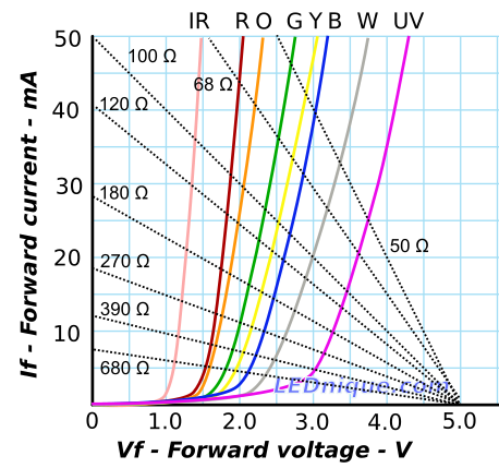
If you have a graph of current versus voltage for a diode you can draw "load lines" on them to solve your question. Here's one I had created for LEDs running from a 5 V supply. The voltages are higher than for a regular diode but the principle is the same.

enter image description here

Figure 1. The simple circuit.

enter image description here

Figure 2. Current versus forward voltage for a range of LEDs of different colours with load lines for various resistor values. Source: Loadline resistance graphic tool.

If we take the 100 Ω case of Figure 2 and the UV LED (because it is closest to the 5 V supply voltage) we can make the following observations:

  • If Vf is 0 V then there is 5 V across R1 and the current would be 5/100 = 50 mA. The 100 Ω load line starts at (0, 50).
  • If Vf is 5 V then there is 0 V across R1 and the current would be 0 mA. The 100 Ω load line ends at (5, 0).
  • To see what current flows through the UV LED on a 5 V supply with 100 Ω for R1 just find the intersection of the load line with the UV curve. This is at 3.5 V and 15 mA.
  • Given either the resistor value or the desired current you can quickly estimate the other from the graph.

So, back to your question:

If a diode is in series with a resistor and a voltage source that is set at the exact forward voltage drop value of the diode, what will be the voltage drop across the resistor?

Hopefully it's clear now that a diode doesn't have an "exact" forward voltage drop.

It can’t be zero but I’m guessing it must be close. We have learned that normally you would subtract the forward voltage (0.7 V) from the loop but this circumstance doesn’t make sense to me.

Your hunch is correct. You just need to remember that the current versus Vf graph is a curve, not a right angle.

\$\endgroup\$
11
\$\begingroup\$

Diode is a nonlinear element. For your question, assuming an ideal diode:

  1. Diode when forward biased start conducting completely at 0.7 V.

  2. The voltage source is also precisely set to 0.7 V.

  3. The voltage drop across the R appears when there is a flow of current. The current can't flow since there is no voltage difference across the resistor. Drop is zero across the resistor.

Assume ideal Voltage source as well as a zero resistance for the resistor.

  • The current will be zero if voltage is less than or equal to 0.7 V.
  • The current will be infinite if voltage is greater than 0.7 V.
\$\endgroup\$
0
5
\$\begingroup\$

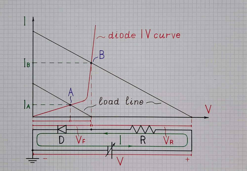
The problem here is that OP thinks the voltage drop across the diode is VF (about 0.7 V); so, including a voltage source with the same voltage VF, the result should be zero. However, this is valid if sufficient current flows through the diode (e.g., it is a basic requirement for a Zener voltage stabilizer)... and this requires higher supply voltage, which in this case is nowhere to be taken. As a result, as professionals say, "the diode is not properly biased". I have graphically illustrated this situation in Fig.1. Let's examine it.

Fig. 1 - Unbiased diode

Fig. 1. To work properly in the vertical part of its IV curve, the diode should be properly biased

To work properly (in the almost vertical part of its IV curve), the diode requires more significant current (IB) that can be obtained by higher voltage V and the resistance R. As a result, the load line (in brown) intersects the diode IV curve in the middle of the vertical part - the so-called "operating point" B, and the voltage drop across diode is VF = 0.7 V.

However, the OP's input voltage is only VF. So the load line has significantly moved to the left... and now it intersects the diode IV curve in the (almost) horizontal part of the IV curve - point A (the operating point has moved from the B to A position). Now the current IA is insufficient... and the voltage drop across diode is less than VF.

So, formulated in this way, the question has no practical value. It is just an undesired situation in the analog diode applications. But if somehow the diode is properly biased, the OPs question makes sense and can illustrate many interesting and important applications.

"Biasing" simply means "adding" constant voltage to the existing input voltage (V+ in the figure). If there was not a ground, there would be only one way to do it. But as we usually ground the diode (as in the figure), we can do it in two possible ways - from the side of anode ("pulling" it up) and from the side of cathode ("pulling" it down). Let's consider the latter as more interesting and more easily implemented - Fig. 2.

Fig. 2 - Biased diode

Fig. 2. Biasing a diode from the side of cathode

To bias the diode, we have connected another (but negative) voltage source V-. As we can see from the voltage picture (red bars), we can adjust V+ to make it equal to VF of operating point C (in the middle of the vertical part). As a result, the "output" voltage (of the cathode) is zero (the so-called "virtual ground"). As though the voltage V+ has neutralized the voltage drop VF across the diode... and the total voltage of this network consisting of V+ and D is zero. Figuratively speaking, we can think of the network as of "ideal diode" with zero voltage drop VF. Moreover, with more imagination, we can consider the voltage source V+ as a kind of "negative diode" -D that removes the "positive diode" D. It is negative since it adds voltage while the ordinary diode is positive since it subtracts voltage.

The name of this technique (can be) "voltage compensation"... where we compensate an undesired voltage drop by equivalent voltage in a series manner. It can be passive if VF is compensated by another VF across an equal diode. This technique is widely used to bias output (op)amp complementary stages with diode and "active diode" networks connected between transistor bases. Another application can be found in H&H AE (page 52, Fig. 1.93) where a diode log converter is compensated this way.

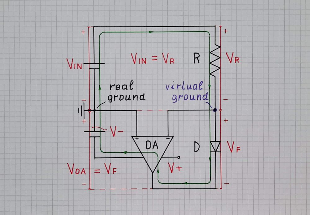
However, quite more interesting is the active voltage compensation. We can see it in the circuit of an op-amp log converter if we draw it in a more unusual way - Fig. 3. The elements with positive voltages are drawn above the zero voltage line (ground); the elements with negative voltages are drawn below the zero voltage line.

Fig. 3 - Diode log converter

Fig. 3. In the op-amp log converter, the op-amp compensates VF by adding equal voltage -VF

The op-amp acts as the variable voltage source V+ from Fig. 2 above. It "goes" below zero to add voltage VF in series to the diode. As a result, the "output" voltage of the anode is zero (virtual ground)... the op-amp has neutralized the voltage drop VF across the diode... Figuratively speaking, we can think of the combination of (properly supplied) op-amp, power supply V- and imperfect diode as of an "ideal diode" with zero voltage drop VF... or, as above, we can think of the op-amp as a kind of "negative diode"-D that removes the "positive diode" D...

\$\endgroup\$
3
\$\begingroup\$

The voltage drop on a (real) diode is not fixed, but varies with current, temperature, and perhaps other conditions.

While in your circuit you slowly raise the source voltage, the voltage drop on the diode will also raise: it will be never greater than the source (otherwise you have a generator, not a diode). So a current flows, the resistor drops some voltage, and the system finds (automatically) an equilibrium because with less current and voltage, the diode lowers its voltage drop.

\$\endgroup\$
3
\$\begingroup\$

I think there is a much simpler "Electronics 1" answer to your question.

The voltage across the diode and the voltage across the resistor must sum to that of the voltage source. Thus if the voltage drop across the diode is its forward voltage drop (which would be the case in a simple ideal diode model - and that's the simplification I'm suggesting you are meant to make), then the voltage drop across the resistor is zero. A corollary is that no current flows.

Several other answers will tell you why this simplification is not always accurate, but given you've supplied no other data about the diode (presumably because you've been given one), I'd suggest you are meant to be making the above simplification.

\$\endgroup\$
0
\$\begingroup\$

There is a voltage vs current chart for the diode. Presuming a specific voltage and current level on the chart it can be determined that an infinitesimal change in voltage and current represents an equivalent resistance, therefore in series with the current limiting resistor. You can also guesstimate the led voltage, presume voltage current and power across the resistor based on Vcc minus this voltage, look up the voltage on the chart at this current and adjust current estimations based on this revised Vcc minus this adjusted junction voltage value accordingly. Keep in mind because of the increase in junction voltage due to temperature you are going to be approximate.

\$\endgroup\$

Your Answer

By clicking “Post Your Answer”, you agree to our terms of service and acknowledge you have read our privacy policy.

Not the answer you're looking for? Browse other questions tagged or ask your own question.