0
\$\begingroup\$

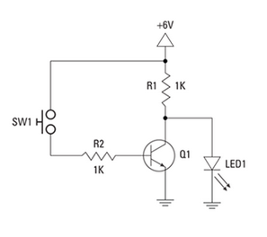
I have built the following circuit (obtained from Electronics All-in-One For Dummies (For Dummies 2nd Edition))

logical not circuit

It works quite well. When the the momentary button (normally open) is not pushed the LED is on.
When I push the button, I see the LED turn off.

However, for a bit I accidentally had my 2n2222a NPN BJT transistor (datasheet) oriented backwards so that :

  1. the emitter was connected to the LED
  2. and the collector was connected to ground

The circuit still worked exactly as expected.
Can someone explain why it would still work the same with the transistor in the incorrect orientation?

\$\endgroup\$
5
  • \$\begingroup\$ Try it with R2<=100k \$\endgroup\$
    – D.A.S.
    Commented Feb 9, 2020 at 21:56
  • \$\begingroup\$ @TonyStewartSunnyskyguyEE75 I changed Rb to 100k and in reverse active mode it still works. This is far less current than I thought would open the emitter-collector circuit. Maybe that's the point you were making? \$\endgroup\$
    – raddevus
    Commented Feb 9, 2020 at 22:05
  • 1
    \$\begingroup\$ Yes. You can expect current gain to reduce to 10% when saturated but here you only need to go below Vf of LED, so current gain is still high \$\endgroup\$
    – D.A.S.
    Commented Feb 9, 2020 at 22:06
  • \$\begingroup\$ it just feels wrong to turn off an LED by short circuiting it \$\endgroup\$
    – jsotola
    Commented Feb 9, 2020 at 23:11
  • \$\begingroup\$ @jsotola Yeah, yet these are foundational logic circuit building blocks you see in TTL and RTL circuits. You can see more examples of this short-circuiting idea at: en.wikipedia.org/wiki/Inverter_(logic_gate) Definitely looks odd first time you see them though. \$\endgroup\$
    – raddevus
    Commented Feb 9, 2020 at 23:30

2 Answers 2

4
\$\begingroup\$

The NPN transistor is still a NPN transistor if you read it either ways. The mode is called reverse active mode.

The doping levels of collector, emitter, base are different hence the performance will be different. The gain will be very poor and also the voltage that can be applied across the terminals will vary from the datasheet.

\$\endgroup\$
3
  • \$\begingroup\$ Because you gave me the term "reverse active mode" I now was able to find this helpful item with an advanced explanation: electronics.stackexchange.com/questions/29756/… \$\endgroup\$
    – raddevus
    Commented Feb 9, 2020 at 17:47
  • \$\begingroup\$ I'm going out to measure the vorlage across the pond straight away! \$\endgroup\$
    – Transistor
    Commented Feb 9, 2020 at 21:49
  • \$\begingroup\$ @Transistor pond measurements :P my eyes ..updated \$\endgroup\$
    – User323693
    Commented Feb 10, 2020 at 0:24
1
\$\begingroup\$

The circuit works with the transistor connected "backwards" because the base current is way more than is needed for a normally connected transistor. R2 should be 8.2K if the transistor is connected correctly.

\$\endgroup\$
0

Your Answer

By clicking “Post Your Answer”, you agree to our terms of service and acknowledge you have read our privacy policy.

Not the answer you're looking for? Browse other questions tagged or ask your own question.