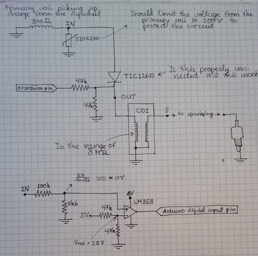
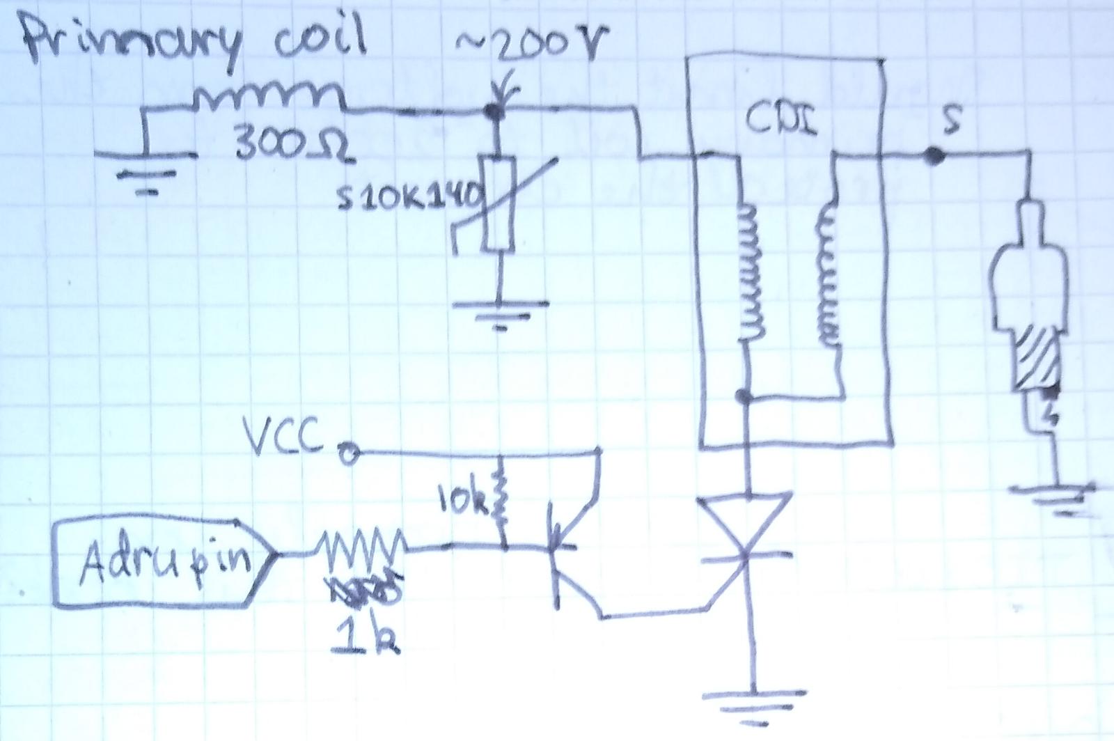
I am trying to design an RPM limiter for my CDI operated 2 stroke engine (Tomos A35). Some people reported that just connecting a capacitor to the primary coil also limits the RPM, but will eventually break your ignition coil. That is why I came up with the following solution:
Here is the same circuit drawn in EAGLE:

The flywheel has magnets and rotates, thereby inducing a charge in the ignition coil. This creates periodic voltage spikes which are sent to the CDI (which has been drawn a bit simplified here). In the original situation, the points IN and OUT are one. In the new situation I want to use a thyristor to either block this voltage spike or pass it. To do so, I need to count the amount of voltage spikes per time unit.
On the bottom I use an opamp (that can take up to 32V on its inputs) as a comparator to protect the arduino. The range of IN at which the opamp triggers without blowing up is now 47 to 603 volts, which should be fine I think. With this circuit, I should be able to count the amount of voltage spikes per second.
The trigger voltage of the TIC126D is max 1.5V I read from the datasheet, so it can be operated from the arduino without further ado.
I am, however, a bit fuzzy on how to select all of these resistor values. So I am asking you for help on that. The values that are there now are based on examples I found on the internet. Also, general tips about the design are very welcome.
EDIT 11/02/2020, 13:45 As DKNguyen pointed out, I am indeed using the thyristor as if it were an NMOS transistor. I could use the thyristor to interrupt the ground wire coming out of the CDI, but this would turn the two coils in there into two inductors (the coils have a common ground that is inside the CDI, there's just nothing I can do about this). Also, I added a PNP transistor to protect the Arduino from drawing too much current.


