6
\$\begingroup\$

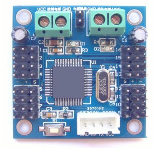
What is the metallic component, labeled Y1, just at the right of the integrated circuit and at the left of the small C4 and C5 capacitors?

When I search for “N24.000” on Google, I find only other boards with the same component, but no information about the component itself.

If I search for “electronic component N24,” all I find are references to a bipolar transistor, however the component has only two connectors and therefore is not a transistor.

Searching for “7C20PF” doesn't give anything useful either.

enter image description here

\$\endgroup\$
2
  • \$\begingroup\$ Besides the obvious answer, what is this board? I see the serial port connector and VCC terminals. The rest I'm assuming are lots of inputs and outputs. What type of sensors was this expecting? I'm always on the lookout for another data logger. \$\endgroup\$ Commented Feb 17, 2020 at 17:07
  • \$\begingroup\$ @Arseni looks like a servo motor Control board. Not the same, but looks similar: m.aliexpress.com/item/32813133679.html \$\endgroup\$ Commented Feb 18, 2020 at 12:46

2 Answers 2

25
\$\begingroup\$

What is the metallic component, labeled Y1, just at the right of the integrated circuit and at the left of the small C4 and C5 capacitors?

It is a 24 MHz crystal (hence the "24.000" marking on the top).

The component designator letter "Y" is commonly used for crystals.

Capacitors C4 and C5 will be the load capacitors for the crystal.

\$\endgroup\$
5
  • \$\begingroup\$ C4&C5, poor component placement. Should be between the crystal and the µC. \$\endgroup\$
    – Janka
    Commented Feb 17, 2020 at 0:00
  • 8
    \$\begingroup\$ at 24Mhz that's unlikely to make a measurable difference, \$\endgroup\$ Commented Feb 17, 2020 at 5:12
  • 2
    \$\begingroup\$ @Jasen Just curious. Around what frequency does it start to be of a concern? \$\endgroup\$
    – Aloha
    Commented Feb 17, 2020 at 7:03
  • \$\begingroup\$ @PNDA The general rule of thumb I hear is that traces shorter than 1/10 of a wavelength don't really matter. That would be about 60cm (assuming the signal travels at half of light speed). \$\endgroup\$ Commented Feb 17, 2020 at 10:26
  • \$\begingroup\$ 60 or even 6cm would probably create parasitic capacitance more than the 20pf load required for the crystal. And PCB track is not a very good capacitor for a timing circuit. \$\endgroup\$
    – fraxinus
    Commented Feb 17, 2020 at 11:21
11
\$\begingroup\$

It is a clock crystal as part of the MCU clock circuit . That is also common for reference designators "Y"

24.000 indicates frequency 20pf indicates loading

C4 and C5 are capacitors used as part of the oscillator circuit.

\$\endgroup\$
3
  • \$\begingroup\$ That's a little surprising. In undergrad EE classes, crystal oscillators were usually labelled either as XTAL or simply X. So why switch that over to Y? \$\endgroup\$
    – Paddy
    Commented Feb 17, 2020 at 15:09
  • 1
    \$\begingroup\$ @PradyothShandilya generation Y took over. IEEE 315 has it in it's list like this with Y. And the PDF looked like really old (1975), but there are other standards around and lot's of personal preference. \$\endgroup\$
    – Arsenal
    Commented Feb 17, 2020 at 16:58
  • \$\begingroup\$ @PradyothShandilya perhaps to disambiguate between crystal (Y) and Crystal oscillator (XO) \$\endgroup\$
    – crasic
    Commented Feb 18, 2020 at 6:02

Not the answer you're looking for? Browse other questions tagged or ask your own question.