0
\$\begingroup\$

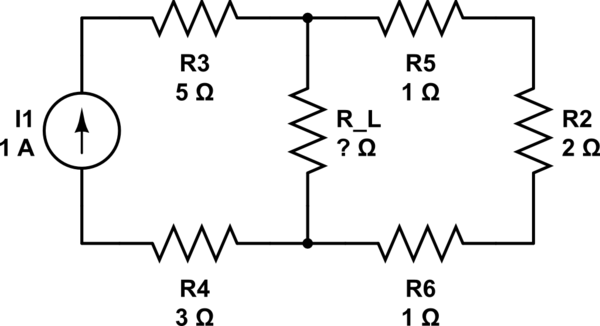
What is the \$R_L\$ value can maximize the power of \$R_L\$?

schematic

simulate this circuit – Schematic created using CircuitLab

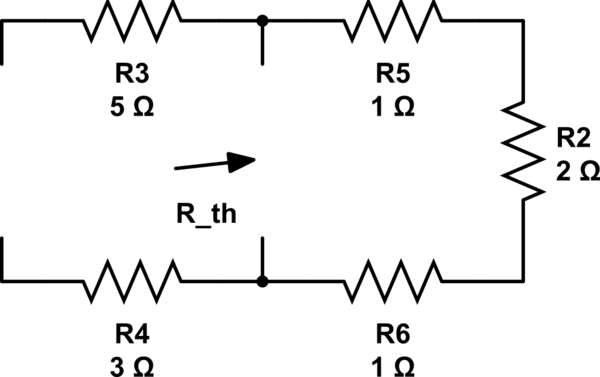
The solution:

schematic

simulate this circuit

\$R_{th}=1+2+1=4\$,so when \$R_{L}=R_{th}=4,\$ it has the maximal power

I want to ask

1.Why can we seem the current source as a open circuit,and voltage source as a close circuit?

2.Why can we know when \$R_{L}=R_{th}=4,\$ it has the maximal power?

3.why is the \$R_{th}=1+2+1\$,not the \$R_{th}=1+2+1+5+3\$ or \$R_{th}=5+3\$ ?

\$\endgroup\$
2
  • \$\begingroup\$ What is the definition of \$R_{th}\$? That may help you solving 1 and 3 \$\endgroup\$
    – Huisman
    Commented Feb 17, 2020 at 8:58
  • \$\begingroup\$ Regarding 2: Draw out \$V_{th}\$ and \$R_{th}\$ and connect \$R_{load}\$. You know \$R_{th}\$, but do assume you do not know \$R_{load}\$ yet. Write down the equation for the power (dissipation) of \$R_{load}\$ and solve it for the maximum power. \$\endgroup\$
    – Huisman
    Commented Feb 17, 2020 at 9:00

4 Answers 4

2
\$\begingroup\$

1.Why can we seem the current source as a open circuit,and voltage source as a close circuit?

Short answer: By definition.

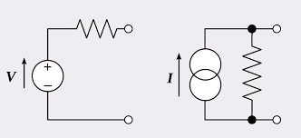
A real voltage source is modeled as an ideal source with small output impedance connected in series. And, a real current source is modeled as an ideal source with large output impedance connected in parallel:

enter image description here

Look at the left-most circuit: If the series resistor has a non-zero resistance then there will be a voltage drop across that resistor when a load resistor is connected across the output terminals (Example: Assume the source is 5V, the series resistance is 1 Ohm and you loaded the source with 5 Ohms. You expect 5V/5 Ohms = 1Amps. But no, the voltage will be divided according to Ohm's law.). That is what happens in practice, actually. But in theory, the series resistor is zero. That's why we replace a voltage source with zero-resistance (i.e. short circuit).

Now look at the right-most circuit. If the parallel resistor has a finite resistance then the current will be divided when a load resistor is connected across the output terminals.

2.Why can we know when RL=Rth=4, it has the maximal power?

It comes from maximum power transfer equation. It states that the load resistance should be equal to the source resistance. You can prove this by yourself (by solving a simple derivative that equals to zero). In the equivalent circuit, source resistance is, of course, R5 + R6 + R2.

3.why is the Rth=1+2+1,not the Rth=1+2+1+5+3 or Rth=5+3 ?

Now you should see why.

\$\endgroup\$
2
  • 1
    \$\begingroup\$ I would clarify your first sentence: "A real voltage source is modeled as an ideal source..." \$\endgroup\$ Commented Feb 17, 2020 at 12:55
  • \$\begingroup\$ @ElliotAlderson you are right, thanks. Fixed. \$\endgroup\$ Commented Feb 17, 2020 at 12:57
1
\$\begingroup\$

Why can we see the current source as a open circuit and voltage source as a close circuit?

If you had a 1 amp current source, that could be approximated by 10 volts in series with 10 ohm and improved by 100 volts in series with 100 ohm and improved again by 1000 volts in series with 1000 ohms. Do you see where this is going?

Why can we know when RL=Rth=4, it has the maximal power?

Resistors in series with a current source have no affect on the current delivered. You should realize that from part 1 of this answer so, R3 and R4 can be replaced by short circuits.

Do you now see why Rth = R5 + R6 + R2?

\$\endgroup\$
1
  • \$\begingroup\$ So much messing around re-quoting the op due to amendments in the question that were not really required. Sorry Mr Reinstate Monica person; your amendments to my question were right but, due to me not realizing that @jusaca had amended the question but forgot to dutifully amend any quotes in answers, I rejected them. Now I have to redo them. Note to Jusaca - don't fiddle unless you are prepared to do the full job on quotes in answers. \$\endgroup\$
    – Andy aka
    Commented Feb 17, 2020 at 9:51
0
\$\begingroup\$

The definition of a current source is that the output current will not vary with a varying load.

For a resistive load, this means that \$V_{load}\$ can vary while \$I_{source}\$ does not vary.

We can solve this using Ohm's law.

Provided the source is in its compliance range (the range of output voltage it can support), then the dynamic output resistance \$ \frac {\delta V} {\delta I}\$ is, for a varying load, some non zero \$ \delta V\$ with zero \$ \delta I\$ which yields \$\frac {\delta V} {0}= \infty \$ for a perfect source.

The same reasoning can be used for a voltage source where the output voltage does not vary with load so the dynamic output resistance is \$ \frac {0} {\delta I} = 0\$

Real sources are not quite infinity (for a current source) or zero (for a voltage source) but they can be modeled as such with a resistor to show how they deviate from the perfect model (series for a voltage source, parallel for a current source).

\$\endgroup\$
0
\$\begingroup\$

Well, the other people who answered your question have shown why it is the case. Now use the math so show what the equations tell us. We have the following circuit:
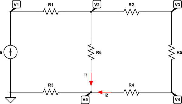
schematic

simulate this circuit – Schematic created using CircuitLab

Using KCL, we can write:

$$\text{I}_\text{i}=\text{I}_1+\text{I}_2\tag1$$

Using KVL, we can write:

$$ \begin{cases} \text{I}_\text{i}=\frac{\text{V}_1-\text{V}_2}{\text{R}_1}\\ \\ \text{I}_2=\frac{\text{V}_2-\text{V}_3}{\text{R}_2}\\ \\ \text{I}_\text{i}=\frac{\text{V}_5}{\text{R}_3}\\ \\ \text{I}_2=\frac{\text{V}_4-\text{V}_5}{\text{R}_4}\\ \\ \text{I}_2=\frac{\text{V}_3-\text{V}_4}{\text{R}_5}\\ \\ \text{I}_1=\frac{\text{V}_2-\text{V}_5}{\text{R}_6} \end{cases}\tag2 $$

I used Mathematica to solve this system of equations, and it gave me:

In[1]:= FullSimplify[
 Solve[{Ii == I1 + I2, Ii == (V1 - V2)/R1, I2 == (V2 - V3)/R2, 
   Ii == V5/R3, I2 == (V4 - V5)/R4, I2 == (V3 - V4)/R5, 
   I1 == (V2 - V5)/R6}, {I1, I2, V1, V2, V3, V4, V5}]]

Out[1]= {{I1 -> (Ii (R2 + R4 + R5))/(R2 + R4 + R5 + R6), 
  I2 -> (Ii R6)/(R2 + R4 + R5 + R6), 
  V1 -> (Ii (R1 + R3) (R2 + R4 + R5) + 
    Ii (R1 + R2 + R3 + R4 + R5) R6)/(R2 + R4 + R5 + R6), 
  V2 -> (Ii R3 (R2 + R4 + R5) + Ii (R2 + R3 + R4 + R5) R6)/(
   R2 + R4 + R5 + R6), 
  V3 -> (Ii R3 (R2 + R4 + R5) + Ii (R3 + R4 + R5) R6)/(
   R2 + R4 + R5 + R6), 
  V4 -> (Ii (R3 (R2 + R4 + R5) + (R3 + R4) R6))/(R2 + R4 + R5 + R6), 
  V5 -> Ii R3}}

The power in resistor \$\text{R}_6\$, gives:

$$\text{P}_{\text{R}_6}=\left(\frac{\text{I}_\text{i}\left(\text{R}_2+\text{R}_4+\text{R}_5\right)}{\text{R}_2+\text{R}_4+\text{R}_5+\text{R}_6}\right)^2\text{R}_6\tag3$$

The maximum occurs when:

$$\frac{\partial\text{P}_{\text{R}_6}}{\partial\text{R}_6}=0\space\Longleftrightarrow\space\text{R}_6=\dots\tag4$$

Using Mathematica, gives:

In[2]:= FullSimplify[
 Solve[{D[((Ii (R2 + R4 + R5))/(R2 + R4 + R5 + R6))^2*R6, R6] == 0, 
   R6 > 0 && Ii > 0 && R2 > 0 && R4 > 0 && R5 > 0}, R6]]

Out[2]= {{R6 -> ConditionalExpression[R2 + R4 + R5, 
    R5 > 0 && R4 > 0 && R2 > 0 && Ii > 0]}}

So, the maximum occurs when:

$$\text{R}_6=\text{R}_2+\text{R}_4+\text{R}_5\tag5$$

And the maximum is then:

$$\hat{\text{P}}_{\text{R}_6}=\frac{\text{I}_\text{i}^2\left(\text{R}_2+\text{R}_4+\text{R}_5\right)}{4}\tag6$$
\$\endgroup\$

Your Answer

By clicking “Post Your Answer”, you agree to our terms of service and acknowledge you have read our privacy policy.

Not the answer you're looking for? Browse other questions tagged or ask your own question.