1
\$\begingroup\$

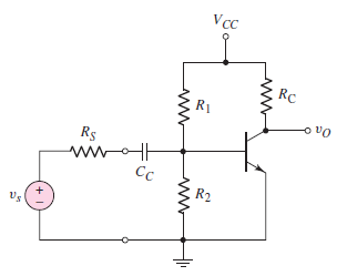
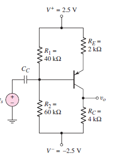
It's not immediately apparent to me as to why the following common-emitter configuration use two supply rails when used in conjunction with a PNP type BJT but the NPN version does not?

PNP CE configuration (from Neamen Microelectronics Circuit Analysis and Design 4th edition)

NPN CE configuration (from Neamen Microelectronics Circuit Analysis and Design 4th edition)

To bias a BJT transistor in the forward active mode we would like the emitter-base terminal to be forward biased and the collector-base terminal to be reverse biased. For an NPN transistor in this common emitter configuration the collector terminal is connected to the positive supply and is therefore reverse biased whilst the emitter sits at a negative potential and is therefore forward biased.

With the PNP transistor the emitter terminal is connected to a positive supply and therefore forward biased whilst the collector is connected to the negative supply rail and therefore reverse biased.

My question is why is it common to see dual positive/negative supplies used with the PNP transistor? Wouldn't it be sufficient just to tie the node which connects R2 and RC to ground?

\$\endgroup\$
3
  • \$\begingroup\$ Just re-label V+ as GND and V- as VCC or -5V. (note for PNP circuitry, the positive terminal is the more logical choice for GND, especially with a common emitter amp) \$\endgroup\$
    – user16324
    Commented Feb 17, 2020 at 18:36
  • 1
    \$\begingroup\$ Is it common to see dual positive/negative supplies with PNP transistors? For the most part PNP transistors are avoided, because for the most part they're not as good as their NPN counterparts. Usually you only see them in theoretical discussions (which may be where the dual supplies crop up) and in circuits that can (for instance) use one PNP where you'd need two or more NPN's to do the same job. \$\endgroup\$
    – TimWescott
    Commented Feb 17, 2020 at 19:02
  • 1
    \$\begingroup\$ Oh -- you also see them in really old circuits, because in the dawn of the transistor age PNP transistors were more common. I'm pretty sure that PNP is the only way to make a point-contact transistor. Just after the point-contact era I'm not sure whether it was easier to make a PNP germanium epitaxial transistor, or whether selling PNPs was dictated by a market that had gotten used to transistors being PNP. \$\endgroup\$
    – TimWescott
    Commented Feb 17, 2020 at 19:04

1 Answer 1

5
\$\begingroup\$

Because these two circuits are differently labeled. That's all.

Both inputs are AC-coupled, so whether you call the most negative voltage in these schematic "ground" or "-2.5V" makes no difference at all.

\$\endgroup\$

Your Answer

By clicking “Post Your Answer”, you agree to our terms of service and acknowledge you have read our privacy policy.

Not the answer you're looking for? Browse other questions tagged or ask your own question.