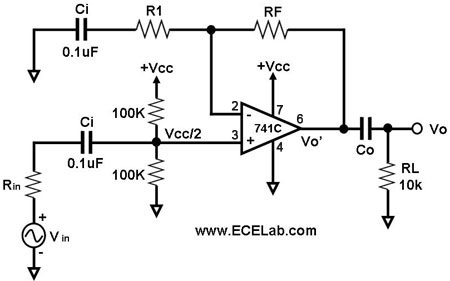
If using polarised electrolytic caps in an amplifier circuit as shown below,

Does it matter which way round I place the caps? If so, why?
Use of electrolytic caps makes about no sens for Ci1 and Ci2 and only for Co if your Vcc is hundreds of volts. ie the leakage characteristics of an ecap will trash any precision you may hope for (and quite a lot that you don't hope for.)
And, 0.1 uF is such a small value for an ecap that you probably need a special licence these days to buy one, if anyone stocks them.
BUT
Ci_connected_to_Vin (components should have unique names) will have net unipolar noisy DC applied as long Vin < Vcc /2 so it is not seeing true AC so a polarised cap can be used, although why you'd use one there is a mystery.
Same applies to Ci_upper but more so.
Co also see a signal always above ground so can be an ecap if you must.
In all cases the ground referenced side should be negative because in use it will always be more negative.
The design of the 741 opamp ocurred a serious fraction of my age ago and they should only be handled with well insulated barge poles.
If ground was half supply instead of V- as shown- as it may be in soime versions of this circuit - then polarised caps would not be suitable at all.
In your case with a single supply in the schematic shown, the Answer (w.r.t. Co) is "Yes" it does matter
Why? Because Vo'-Vo is always positive with an average Vdc = Vcc+/2
Electrolytic caps can handle about 10% of the rated forward voltage in reverse polarity. If you can figure how to avoid approaching this limit, it should be ok. Beyond this leakage current will be limited on circuit impedance before failure.
In your hypothetical example with high impedances (>=10k), ceramic 0.1uF would be fine unless you were looking at seismic signals.
side comment
Are they still teaching with 741's? how archaic but the concept is the same.