5
\$\begingroup\$

I am doing first project with AVR microcontroller ATmega32-A.

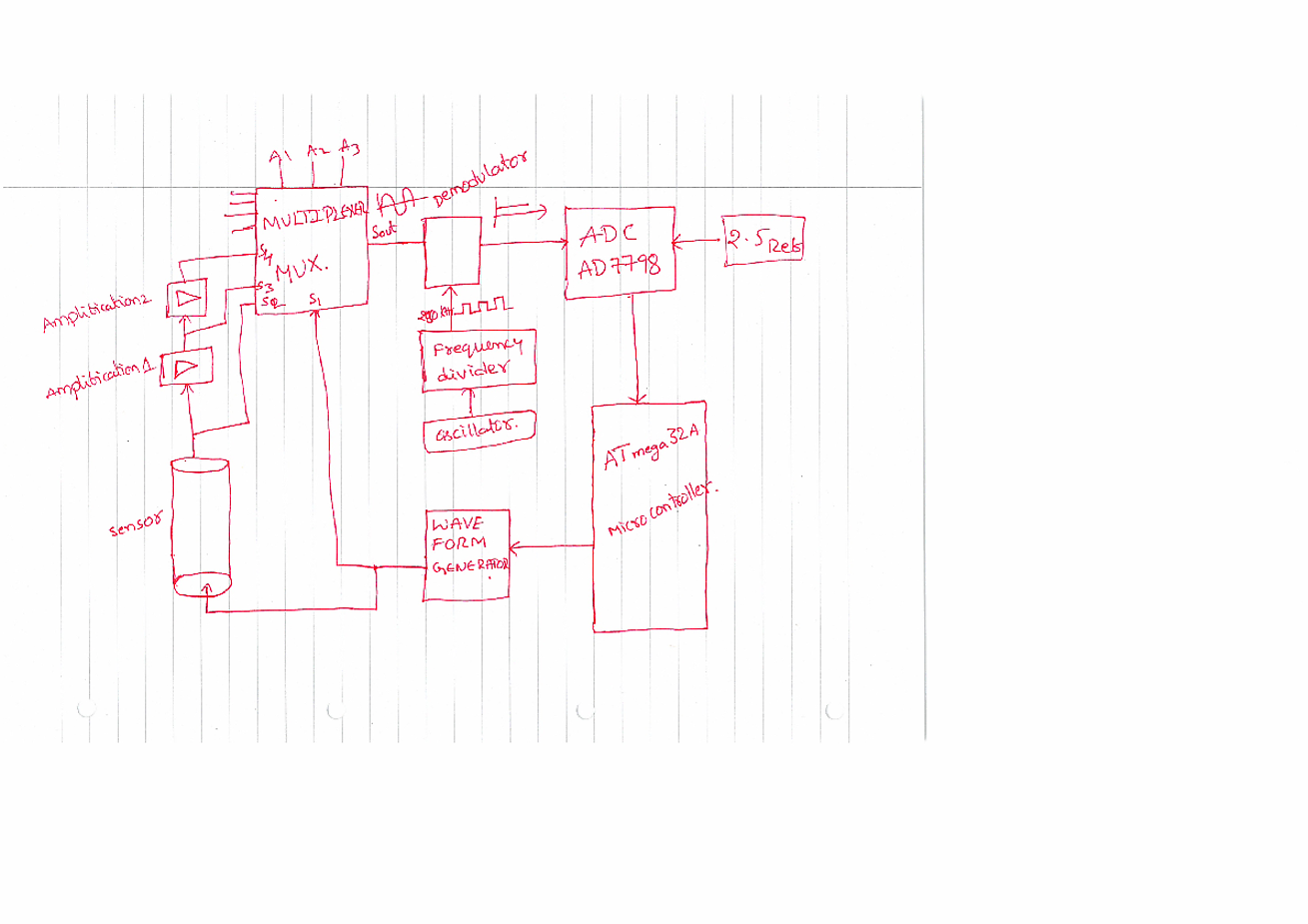
In this project I am interfacing with ADC (AD7798), waveform Generator (AD9833), Multiplexer, Capacitive sensor, Demodulator. I have attached simple block diagram for understanding purpose.

I have to generate sine wave and give it to sensor and in return I will get sensor output with some phase shift. I have to select the sensor output and input signal using Multiplexer. The selected signal will pass through demodulator and to the ADC. Finally ADC to Micro controller.

The concept is I want calculate phase difference between two signals such as Input(Vg) and output(Vr). To calculate the phase value I have implemented algorithm as like below.

Phase of Vg (and so Vr in return) is what I can change, phase of demodulator switch (square signal from frequency divider) is constant and it is my background. I can put both Vg and Vr signal through demodulator.

The algorithm must look like this: put Vg through demodulator, sweep WGP(waveform generator signal phase) until you get highest DC value (now you store how many degrees it takes to get this highest DC, and you calculate Vg amplitude from that). Then put Vr signal through demodulator and also sweep WGP until highest DC value. This phase shift WGP value will be different for Vg and Vr. In result you have the amplitude of both signals and phase difference between them.

I have wrote all functions like To read ADC value, Generate signal with specified frequency, Changing phase of the signal, Phase sweep from 0 to 360 degrees etc.

I have written the fallowing code to select signal using Multiplexer and change the phase of the signal from 0 to 360 degree by one degree at each time and getting the max value of D.C voltage.

From the above code I am able to select signal using "MUXSEL" Command and I am able to sweep phase from 0 to 360 degree, I am able to get max D.C voltage and corresponding Phase value. I am able get above value whenever I add delay.

delay_ms(100);

If I delete this delay from "Phaseshift" function, it is giving nothing even if I reduce also.

If I place that delay then I am getting Max D.C voltage and corresponding Phase after 45 secs. This is too large time in my application. Then I have change channel then it also take 45sec and i have to use this values in other calculation so it takes large time.

I want get Max D.C voltage and corresponding Phase value with in 2 to 3 sec.

Any one help me how to do this. enter image description here
AD7798
AD9833

added spi() function.

    unsigned char spi(unsigned char data) 
      { 
      //Start transmision 
      SPDR = data; 
      //Wait for transmision complete 
      while (!(SPSR & (1<<SPIF))); 
     return SPDR; 
       } 
\$\endgroup\$
12
  • \$\begingroup\$ What does the spi() function (macro?) do? Where is MAX declared? Please link to the datasheet of all the parts you mentioned. My best guess is it takes the AD9833 some time to change phase after you send it the command. If you don't wait for it, you're not measuring what you think you are. But 100 ms seems like an excessively long time for this...have you tried shorter delays? \$\endgroup\$
    – The Photon
    Commented Nov 6, 2012 at 17:49
  • \$\begingroup\$ @ThePhoton I have tried to reduce delay but its not working. The function spi() for spi communication to recive and send data. \$\endgroup\$
    – verendra
    Commented Nov 6, 2012 at 20:12
  • \$\begingroup\$ Does spi() set up registers to control a peripheral and then exit; or does it wait for the communication to complete before exiting? \$\endgroup\$
    – The Photon
    Commented Nov 6, 2012 at 20:24
  • \$\begingroup\$ @ThePhoton Now you can see what is spi() function. I have edited. \$\endgroup\$
    – verendra
    Commented Nov 6, 2012 at 22:12
  • \$\begingroup\$ Why can't you use a time-interval counter to measure phase directly with good filtering and linear amplifiers to get 16 bit resolution for 6 decade resolution averaged in 1 second. \$\endgroup\$
    – D.A.S.
    Commented Nov 7, 2012 at 6:05

2 Answers 2

1
\$\begingroup\$

Your block daigram shows no relationship between the Oscillator/Divider and the Waveform generator, but these must be optimized for synchronous mixing.

Can you try a simple approach?

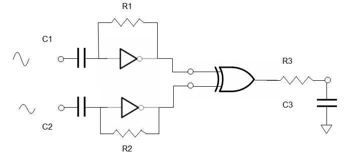
To mix the the sine input and output, may I suggest the classic 180deg range XOR mixer which is commonly known as a Type I PLL phase detector. The inputs are the same frequency and the output is the difference phase and sum frequency ( + harmonics) so a LPF must be chosen to easily suppress the 2f components yet provide fast tracking of phase vs voltage.

enter image description here let R1C1 = R2C2 = R3/C3 = 1000/f = 1000/250KHz = 4ms let R1 = 1~10 MΩ, Let R3 ~ 1KΩ to drive ADC use buffered inverters '04 and '86 XOR

Average ADC readings to achieve desired resolution and noise reduction by √n samples.

\$\endgroup\$
7
  • \$\begingroup\$ I have small doubt Can i measure phase difference between i/p(sensor input)and o/p(sensor output) as well as peak voltages of both signals using the above circuit. \$\endgroup\$
    – verendra
    Commented Nov 10, 2012 at 20:52
  • \$\begingroup\$ You can assume your input is constant (if verified) and still measure your output amplitude with this as phase ( 2 channels.) \$\endgroup\$
    – D.A.S.
    Commented Nov 10, 2012 at 21:07
  • \$\begingroup\$ I don't know what is the input signal amplitude. Is there any possibility that I can measure both signal amplitude as well as phase difference between them. I can change my hardware with that. \$\endgroup\$
    – verendra
    Commented Nov 10, 2012 at 21:24
  • \$\begingroup\$ Vin is your sine synth. YOu can measure voltage across Sensor to get difference using a differential Op Amp. \$\endgroup\$
    – D.A.S.
    Commented Nov 10, 2012 at 21:39
  • \$\begingroup\$ I have to use differential amplifier as well as phase detector to get both signals amplitude and phase difference. How can i use phase detector and differential op-amp at a time, or which circuit i have to use first. any suggestions. \$\endgroup\$
    – verendra
    Commented Nov 10, 2012 at 21:50
0
\$\begingroup\$

As I said in a comment, you could use a mixer to do the work in the analog domain. You could use a chip such as a AD831 which work from DC to several MHz. It also contains some OP amps in the same package that you don't need to use.

This works as follow:

Use a waveform generator to get a sine at a defined frequency of 100kHz for instance. Enter it to the fist input of the mixer and also to the sensor input.

Connect the sensor output to the second input of the mixer.

Add a basic low pass filter to the mixer output with a cutoff frequency a lot lower than the sine frequency (let say here at 1kHz).

How it works ? the mixer is a multiplier. Its ideal response is equal to :

$$ V_{out} = A_1cos(\omega_1t)A_2cos(\omega_2t) $$

But here the input frequencies are the same and omega 1 = omega 2 only a phase shift phi exists : $$ V_{out} = A_1cos(\omega t)A_2cos(\omega t + \phi) $$

which can be rewritten : $$ V_{out} = \frac{A_1 A_2}{2} [cos(2\omega t+\phi) + cos( \phi) ]$$ Here we have one therm that changes over time (the one with the 2wt+phi) and one that is constant (the phi alone). Thus, the lowpass filter at the output of the mixer will remove the oscillating term (because its mean is equal to zero) and the resulting voltage only depends of three factors:

  1. The input amplitude (A1) which is fixer here.
  2. The amplitude at the sensor output (A2). You have to check if it changes significantly along the scale of the sensor. Probably not that much.
  3. The phase (phi) that you want to measure.

The output voltage after the mixer and the filter is a "DC" voltage that depends of the phase you want to measure. You don't need to have a fast ADC here. You only measure a quasi DC signal.

I don't have here any tool to draw a schematics. Sorry.

\$\endgroup\$
1
  • \$\begingroup\$ Here I am generating sine wave using spi communication between AD9833 and Micro controller. So I don't know what is the voltage of input and output signals. So first i have to read those two using ADC and then I have to read Mixer output, Am i right. According to your suggestion, If I have A1, A2 and Vout then only I can caluculate Phase (the one with the 2wt+phi). \$\endgroup\$
    – verendra
    Commented Nov 7, 2012 at 13:08

Your Answer

By clicking “Post Your Answer”, you agree to our terms of service and acknowledge you have read our privacy policy.

Not the answer you're looking for? Browse other questions tagged or ask your own question.