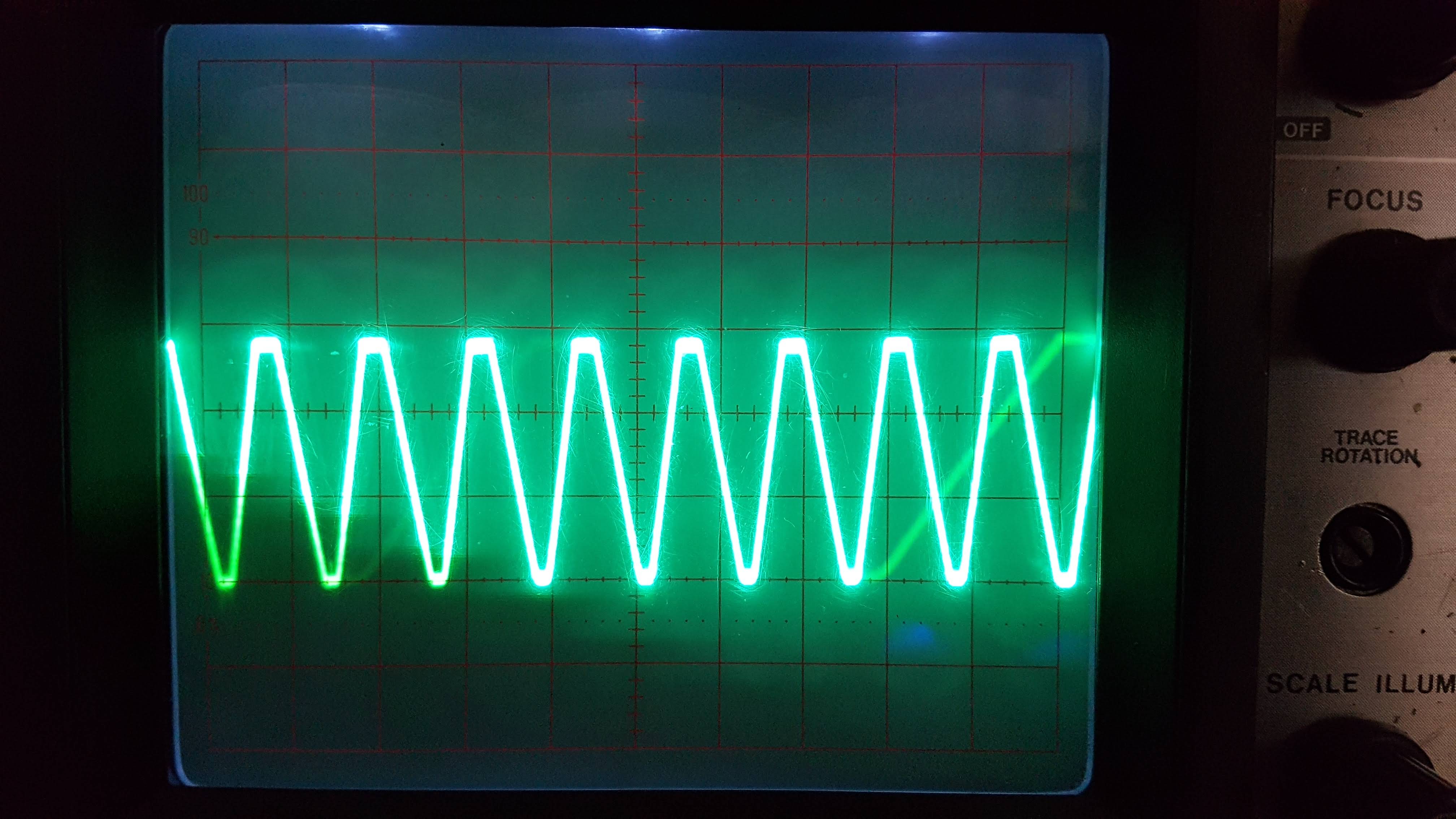
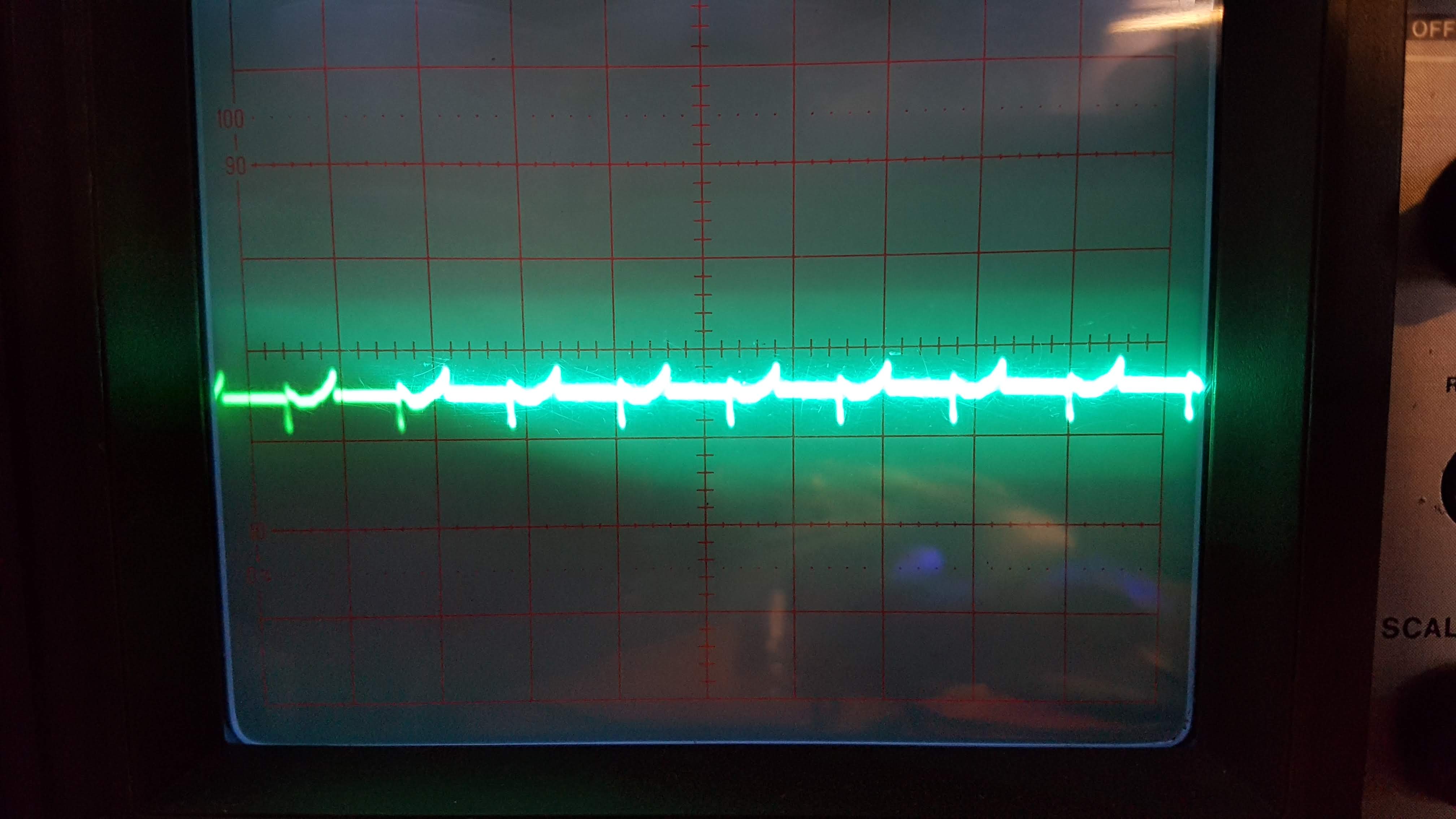
I'm trying to amplify a ~3V signal to ~12V. It's generated using my PC sound card. My circuit works in simulation but in reality, the output is not right at all. What could be going wrong?
-
1\$\begingroup\$ Note that when you start CircuitLab from the button on the editor toolbar and use the Save and Insert button that an editable schematic is saved in your post. No account. No screengrab. No image upload. It has the advantage that we can copy'n'paste your schematic into our answers and edit it. \$\endgroup\$– TransistorCommented Feb 28, 2020 at 13:57
2 Answers
You are using the op-amp on a single-ended supply (positive only) but you are feeding an AC signal in and it is centred around 0 V.
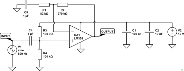
You need to bias the non-inverting input to half-supply (6V) with a pair of resistors and add a DC blocking capacitor to the input.

simulate this circuit – Schematic created using CircuitLab
Figure 1. Modified circuit.
- Your C4 (on the circuit linked in your comments) is a low-pass filter. That's not what you want. You need to block the DC coupling between the INPUT and your biasing arrangement. See the correct location of C4 in Figure 1.
- With R3 and R4 at 10 kΩ the input impedance of your circuit is the parallel combination of the two, 5 kΩ. If this is too low for your source signal then increase to 100 kΩ as shown.
- C5 blocks DC in the feedback divider so that the DC gain becomes \$ 1 + \frac {R2}{R1} = 1 + \frac {R2}{\infty} = 1 \$. This gives the result that the DC bias on the output will be the same as the DC bias on the non-inverting input. (Thanks to @EinerA for the prompt to include this.)
- Your OUTPUT will have a DC bias of 6 V on it. For audio out you need to add a series capacitor their too to block the DC from reaching your amplifier.
-
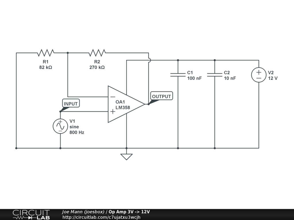
\$\begingroup\$ Such as circuitlab.com/circuit/7ujatxu3wcjh/op-amp-3v-12v ? \$\endgroup\$– JoeCommented Feb 28, 2020 at 14:12
-
\$\begingroup\$ not like that... you biased the -ve supply not the input. \$\endgroup\$– user16324Commented Feb 28, 2020 at 14:14
-
-
\$\begingroup\$ you've misinterpreted "DC blocking capacitor" advice \$\endgroup\$– MapleCommented Feb 28, 2020 at 15:23
-
1
Transistor has shown you how to bias the input, but the circuit will still not work because it is set up to amplify the 6V bias by 4.5. To make the output be centered on 6V you put a capacitor in series with R1. Now the AC signal will be amplified by 4.5, but the 6V DC will see a gain of one.


