0
\$\begingroup\$

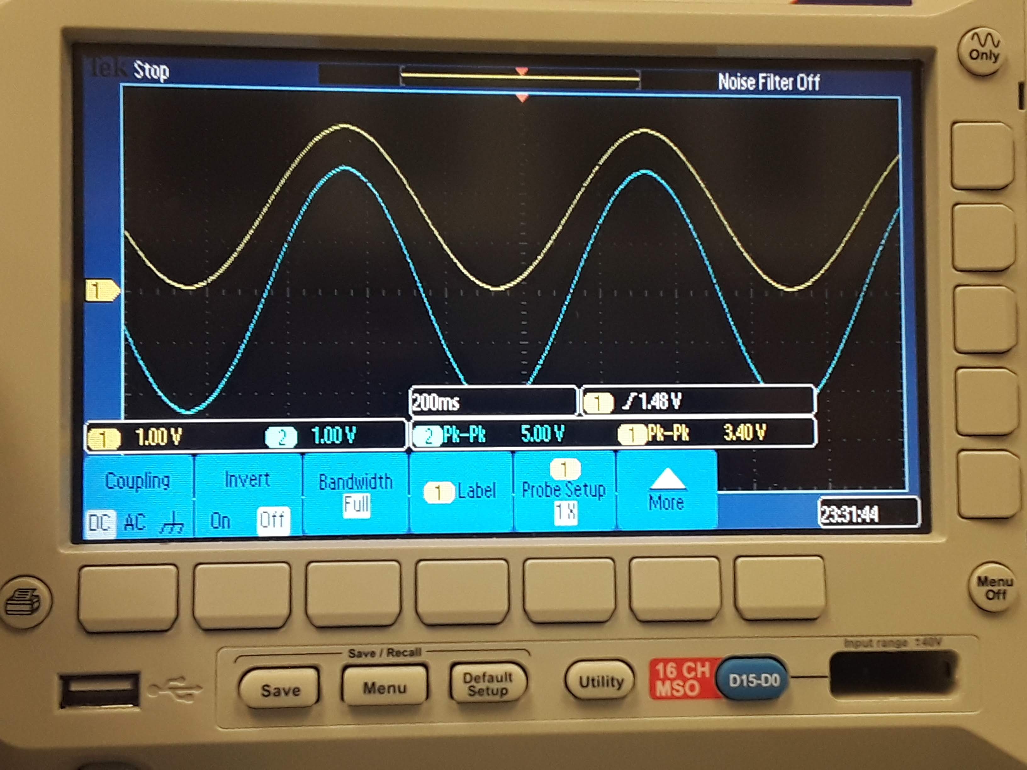
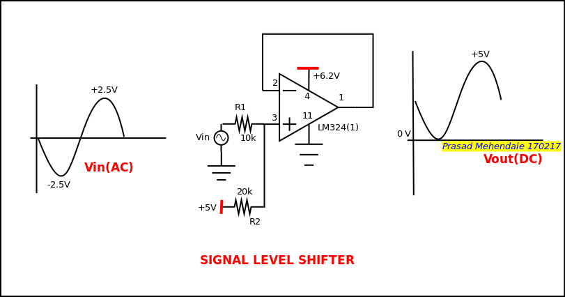
I'm want to digitize an +/- 2.5 V signal using an ADS1256. Since the IC can't take negative voltages I designed a level shifter with a LM324 to translate the +/-2.5 V signal to 0 - 5 V but I was only able to translate up to 3.4 V since the LM324 isn't rail-to-rail. I also realized that the input signal (+/-2.5V) and output signal (0-3V) have different phases. I would like to know if I'm losing resolution or accuracy reading designing the level shifter with a LM324 instead of a rail-to-rail Op-Amp. The frequency range of the signal is 1 to 10 Hz.

The circuit I used is from this website: https://vidnyankendra.org/2017/02/17/level-shifter-using-op-amp/

enter image description here

enter image description here

\$\endgroup\$
3
  • 2
    \$\begingroup\$ For a better answer it would be very helpful if you supplied the schematics of your circuit. There is a tool in the editor which allows you to draw it right here on the site. If you feel that is too much trouble, you can also upload a screenshot of your schematic if it is readable. To further increase the chance for a good answer the "different phases" part could be extended with a number (is it 180 ° or something else) or a photo of your measurement. Reading this might help for accuracy vs resolution (and what you loose). \$\endgroup\$
    – Arsenal
    Commented Mar 2, 2020 at 16:57
  • \$\begingroup\$ I think that frequency and other stuff does not matter if you have waveform distorted (suspect clipped at 3.4V - show the graph). \$\endgroup\$
    – Anonymous
    Commented Mar 2, 2020 at 16:57
  • \$\begingroup\$ Your gain loss isn't due to the opamp: R1 and R2 are attenuating your input to 2/3 Vin, and the opamp has a gain of one. \$\endgroup\$
    – td127
    Commented Jul 31, 2021 at 19:17

4 Answers 4

1
\$\begingroup\$

You don't need an op amp. You can offset the signal with just a resistor network. You wouldn't use the full input range of the ADC but you don't care: it's a 24 bit ADC.

\$\endgroup\$
0
\$\begingroup\$

At -2.5V in, the voltage at pin 3 should indeed be 0V, at +2.5V in, it will be 2.5 + (2.5/3) = 3.3V in. As the op amp is a follower, I would expect the same out. The circuit is doing what it should. You could use a rail to rail opamp, but note that you cannot get the input to +5V with this method of level shifting.

Also note with your circuit that you try to bring the input very close to 0V. Due to resistor tolerances, you might well be clipping the input slightly. Whether this is a problem depends really on the application.

Your circuit is non-inverting, input and output have the same phase.

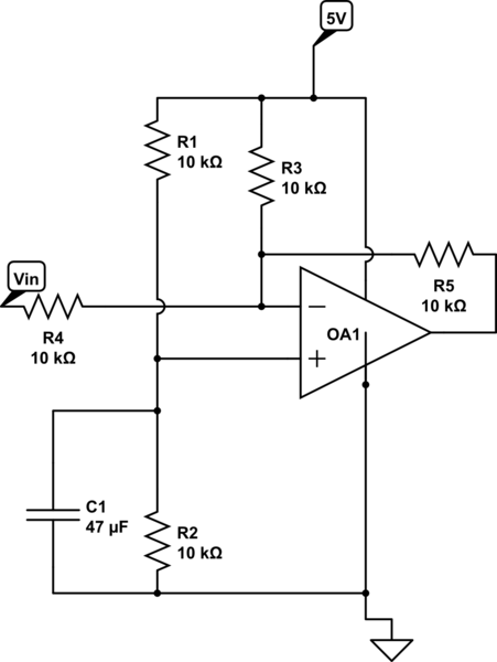
If you really want to get the largest swing, another way might be to generate an artificial mid-rail and sum the input with a DC offset. Schema below:

schematic

simulate this circuit – Schematic created using CircuitLab

The circuit is now inverting, and has lower input impedance. However you are still DC coupled, and you use the full voltage. You can use any opamp that gives rail to rail swing at 5V. You also have a bit more possibility to adjust gain, using the feedback resistor. C1/R2 are sized to provide a stable mid rail at 1Hz.

\$\endgroup\$
1
  • \$\begingroup\$ There is a solution that does not require a cap to charge up. \$\endgroup\$
    – D.A.S.
    Commented Jul 31, 2021 at 14:16
0
\$\begingroup\$

If you are using the same circuit and same input range, the maximum output voltage you will get is \$\frac {2 \times V_{in} +5}{3}\$ (use superposition theorem.) For \$V_{in}\$ =2.5 V (peak), the \$V_o\$ = 3.34V (peak) and 0V (minimum.)

\$\endgroup\$
0
\$\begingroup\$

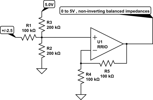
Preferred ratios for 5V Rail to Rail In/Out

schematic

simulate this circuit – Schematic created using CircuitLab

The non-inverting input sees 0 to 2.5 and is then amplified by 1+1=2

\$\endgroup\$
4
  • \$\begingroup\$ The DC offset will be amplified as well. \$\endgroup\$ Commented Feb 22, 2021 at 5:26
  • \$\begingroup\$ Both attenuated /2 and amplified by 2 to get 0 to 5 or were you suggestion something else? @RohatKılıç \$\endgroup\$
    – D.A.S.
    Commented Feb 22, 2021 at 7:05
  • 1
    \$\begingroup\$ Ah okay, sorry, I see now. Input is attenuated by R1 and R2||R3. \$\endgroup\$ Commented Feb 22, 2021 at 8:16
  • \$\begingroup\$ Any questions?? No answer accepted! \$\endgroup\$
    – D.A.S.
    Commented Jul 31, 2021 at 14:18

Your Answer

By clicking “Post Your Answer”, you agree to our terms of service and acknowledge you have read our privacy policy.

Not the answer you're looking for? Browse other questions tagged or ask your own question.