Yes: reciprocity. Excluding certain conditions, a passive circuit will always have symmetrical response, i.e. s12 = s21.
While the impedances on either side of the LC filter need not be equal (or even finite and nonzero -- one of them can be zero or infinity), for the symmetrical case it will be true that the transfer response (that is, the change in output resulting from some change in input) and the self-impedance response (that is, change in output voltage/current from some change in output current/voltage) will share at least the same time constants; and in well-behaved cases (like a Butterworth filter), the responses will indeed be complementary (e.g. for a 1Ω filter, a 1V step at the input, or 1A step at the output, gives the step response (or its difference from a step) of 1V at the output).
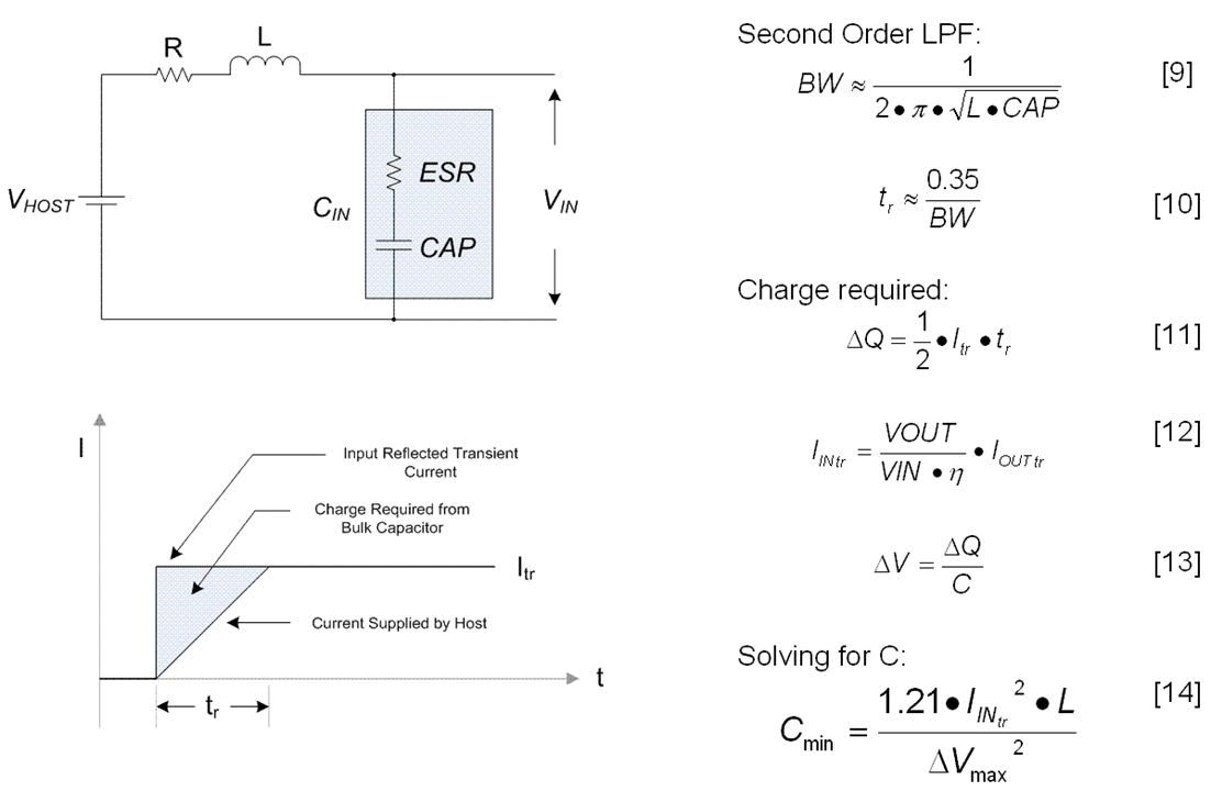
Actually, that's probably still overly general, and, I also haven't specified what kind of "complementary" response that might consist of. But I can afford to be fast and loose in this context, as power supply filter networks are rarely if ever characteristic-impedance matched, and suffer a continuum of source and load impedances, not just one. To deal with this, we typically add resistance of our own, usually lossy capacitors (electrolytics, or others with or without external resistors added in).
In the case where we cannot assume resistive termination, and we insert our own (making an intentionally lossy RLC filter), then we sacrifice the sharpness of a named filter type, while lessening the impact of impedance variation; and by making for example the Q of the filter's poles a maximum of 1 or so, we limit the resonant gain at those frequencies and therefore the transfer and self-impedance response obey they same general rule.
There are still ways to preserve the sharpness of a named filter type (like Butterworth), but it's added expense (e.g., the components required to implement a diplexing filter to give one or both ports a constant-resistance response). Whereas in this context, we really just need some amount of attenuation at EMI/RFI frequencies, very little precision in the cutoff frequency, and we can tolerate significant insertion loss and ripple in the transition band. So the filter tends to be "big enough" and that's that.

