Shear vs bending
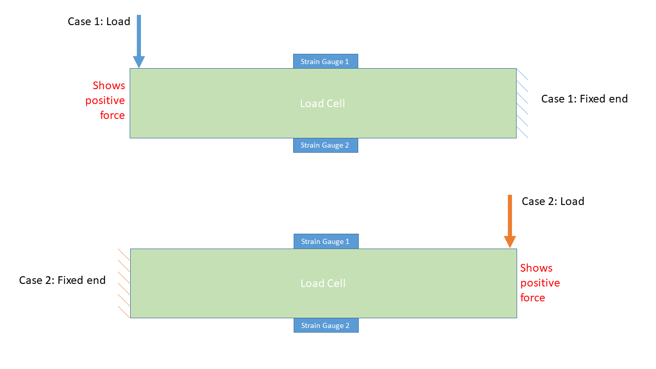
The main reason for the change in signal magnitude when held at left and force applied at right vs when held at right and force applied at left is because it is a shear beam rather than a bending beam.

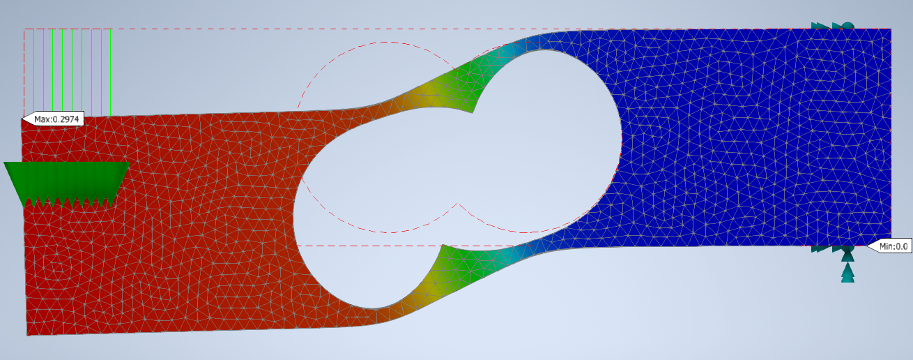
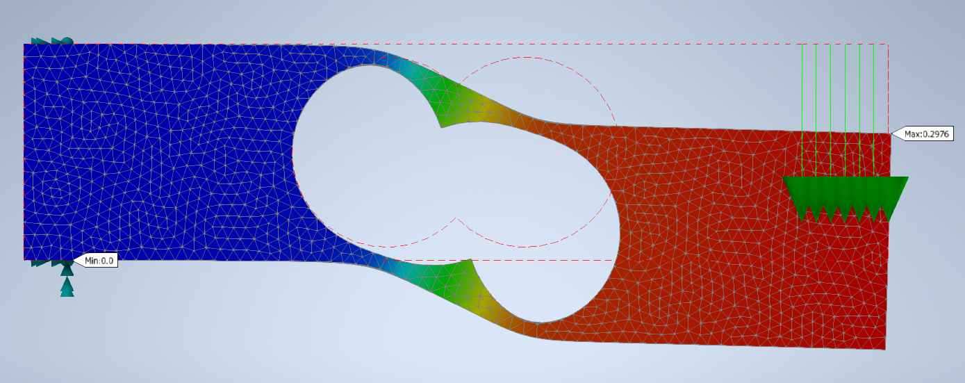
This is a cad model of shear beam.
 held at right and force applied on left
 held at left and force applied on right
In the first simulation figure, left is held at stationary and force is applied at right, if we look at the upper region, the region above right hole has convex shape i.e. lengthening of the region and the region above left hole has concave shape i.e. compression of the region.
In the first simulation figure, right is held at stationary and force is applied at left, if we look at the upper region, the region above left hole has convex shape i.e. lengthening of the region and the region above right hole has convex shape i.e. compression of the region.
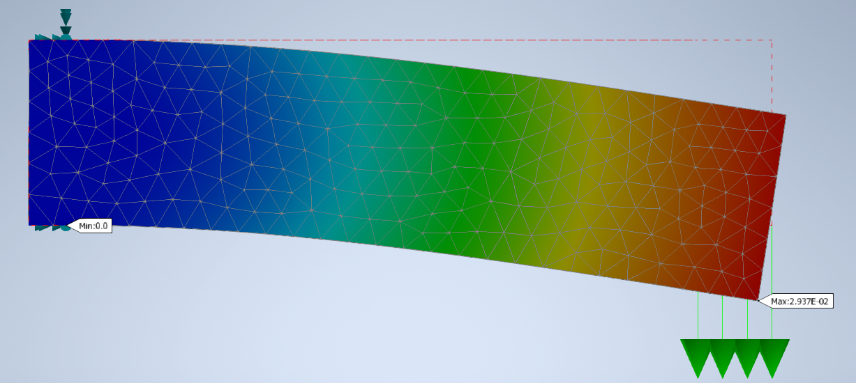
 This is a cad model of bending beam
 held at right and force applied on left
 held at left and force applied on right
Whereas, in case of beam with no holes, we can see that in both cases, the upper region is in tension i.e. elongation and lower region is in compression.
In case of shear beam, the strain gauge is above the hole region. The elongation and compression of region is dependent on which side it is held and force is applied. But for bending load cell, it is not the case.


