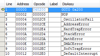
I am trying to understand a HEX file I compiled with Microchip MPLAB X IDE using the Microchip MPLAB XC16 Compiler.
Concerning the MCU, I am targeting the PIC24EP512GU814. However the scope of this question should at least apply to all PIC24 MCUs.
To compile the example HEX below, during the "New Project" wizard, I selected Samples > Microchip Embedded > PIC24 C Template and picked the XC16_24EP512GU814 configuration.
According to the PIC24EP / dsPIC33 Datasheet section 4.1.1 page 48, The memory is segmented into 16-bit words, such that each position (0x0000, 0x0001, ...) contains 16 bits. On the same page of the datasheet, program instructions are said to be 24-bit and span 2 words, such that the most significant byte of the most significant word is zero (00000000b).
This does not appear to be consistent with the compiled HEX file. Here are the first 5 lines of the file, numbered and with the different parts spaced out according to the Intel HEX specifications.
1. :02 0000 04 0000                             fa
2. :08 0000 00 0002040000000000                 f2
3. :02 0000 04 0000                             fa
4. :10 0008 00 c8020000ce020000e4020000d4020000 92
5. :10 0018 00 da020000e8020000ec020000e0020000 42
Consider lines 4 and 5. The first field correctly counts 0x10 (16) bytes in the data field. However, the second field which denotes location in the memory jumps from 0x0008 to 0x0018, or 0x0010 (16) positions.
From my interpretation, this means that this particular HEX file is 8-bit instead of 16-bit because each position is occupied by one byte.
- Is there a way to make the compiler output a 16-bit file?
- Is this file still valid for a 16-bit MCU? How can I interpret the HEX file so that I can manually flash the MCU?

