2
\$\begingroup\$

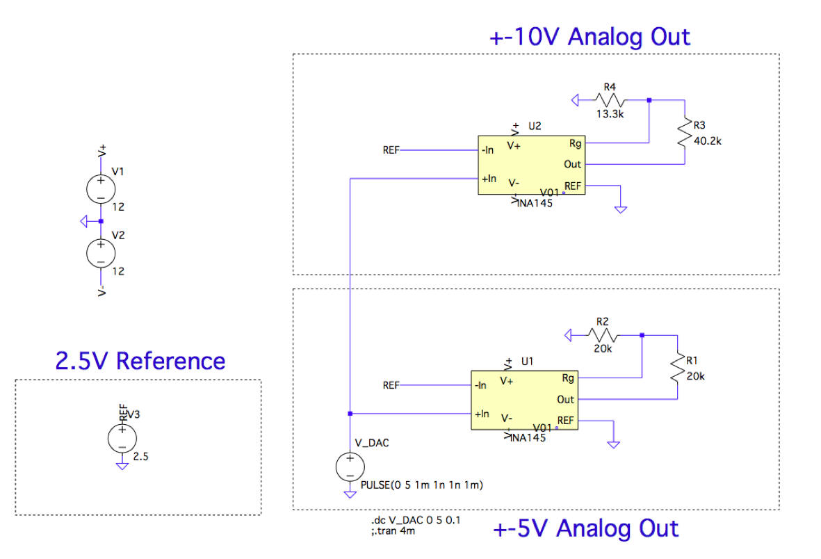
I have a circuit (shown in figure 1) that is supposed to function as a precision analog output. It outputs a DC voltage in the range of either ±10V or ±5V, depending on which gain resistors are used. This analog voltage is intended for use as a reference type of voltage, entailing:

  • High Accuracy ±(0.1% + 1mV): after calibration
  • ~5-10mA of output current maximum
  • DC output, no transient slewing specifications formally stated

Output Circuit

Figure 1: circuit in question.


For +/-5V output the gain is \$G=1+\dfrac{R_1}{R_2}=2\$

For +/-10V output the gain is \$G=1+\dfrac{R_3}{R_4}=4.026\$

Output is \$G\cdot(V_{DAC}-2.5V)\$

After a calibration, the output of the circuit performs to spec. The calibration I used is a simple slope and offset error correcting equation that operates on the code I send to a DAC, shown the code below.

voltage = 5.0;                         // set voltage

cal = (voltage * 1.0047) + 0.0144;     // slope and offset calibration
value = ((cal + 5) * (65535 / 10));    // translate -5 – 5 –> 0–5

if (value > 65535)                     // send max output if value > 2^16
{
    value = 65535;
}

output_MAX5134(value, AO_DAC_0);       // write to DAC output 0

The problem is, if I come back the next day after calibration, there will be an offset present on the output. The gain error is still eliminated, but I will see something like 2.5200V instead of 2.5005V. The thing I can think of is the temperature is effecting things, maybe I have to account for it?


For reference I am using:

1% Tolerance SMD resistors -> should be accounted for in calibration

REF3425 -> 0.05% 2.5V Reference
http://www.ti.com/lit/ds/symlink/ref3425.pdf

INA145 -> Difference amplifier as Unipolar to bipolar converter
http://www.ti.com/lit/ds/symlink/ina145.pdf

MAX5134 -> 16-bit DAC with high linearity
https://datasheets.maximintegrated.com/en/ds/MAX5134-MAX5137.pdf

I am using a u3606A 5-1/2 digit multimeter for voltage measurements


INA145 Gain Error Vs Temp:

enter image description here


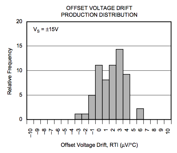
INA145 Offset Voltage Drift Vs Temp:

enter image description here

\$\endgroup\$
3
  • \$\begingroup\$ What is the INA145 offset and drift by specs? \$\endgroup\$ Commented Mar 14, 2020 at 23:08
  • \$\begingroup\$ @MarkoBuršič Added datasheet table/graph. Looking at the numbers I didn't think it be much of an issue. The day to day temperature has stayed relatively constant, but I ideally want to remain accurate under a range of temperatures from ~10C to 30C. Unfortunately, I have no way of testing this board under temp. \$\endgroup\$ Commented Mar 14, 2020 at 23:18
  • \$\begingroup\$ By the way, you have to do float math and then parse into integer math. Example 65535/10=6553. Do always use a decimal point on all float numbers, 5=5.0 ; 65535=65535.0, and so on...else the compiler would choose a type on his own \$\endgroup\$ Commented Mar 14, 2020 at 23:57

1 Answer 1

1
\$\begingroup\$

The INA145 has an input offset of max +/-1mV:

enter image description here

But this offset is the due to manufacturing process and it remains as is, therefore the calibration shall eliminate this issue. Next is the drift, which is measured in few micro volts per celsius, multiplying this with gain you get some very small error.

IMO you do use some resistors that have high TCR, they are not suitable for precision voltage dividers.

\$\endgroup\$
5
  • \$\begingroup\$ The 20kΩ resistors have a TempCo of ±100ppm/°C. Should I shoot for a smaller value? Again the temperatures have been fairly constant, no larger change than 5°C or so. Measurements were also made under no load and after the circuit has been on for some time. \$\endgroup\$ Commented Mar 14, 2020 at 23:42
  • \$\begingroup\$ What does the DMM show on your REF5025? Is it the same, or maybe the DMM error? What about DAC output? \$\endgroup\$ Commented Mar 14, 2020 at 23:47
  • \$\begingroup\$ REF5025 is 2.50028V, same voltage measured at pin of INA145. For a desired voltage out of 2.5V, DAC out is 3.746V. From the INA145 equations, output voltage should be 2.492V, which I confirmed with multimeter. DAC reference voltage is 4.975V. Maybe this is the problem. I seem to remember the output voltage being almost 5V exactly before. Even as I typed this, the 5V ref dropped to 4.972V, and varies to 5.02V if I touch the IC with my finger. \$\endgroup\$ Commented Mar 15, 2020 at 0:19
  • \$\begingroup\$ I believe the issue may be the 5V reference, which is the REF5050. It seems sensitive to temperature (blowing lightly reduces output to 4.969V, touching with finger brings it to 5.02V). I have no such problems with the REF3425. My 10V ref seems to have the same problem (REF5010). I realized my 2.5V ref is the REF3425, not the REF5025, my apologies. \$\endgroup\$ Commented Mar 15, 2020 at 0:24
  • \$\begingroup\$ I will check my soldering connections. I don't believe the voltages should be changing so much. Thank you for the help! \$\endgroup\$ Commented Mar 15, 2020 at 0:39

Your Answer

By clicking “Post Your Answer”, you agree to our terms of service and acknowledge you have read our privacy policy.

Not the answer you're looking for? Browse other questions tagged or ask your own question.