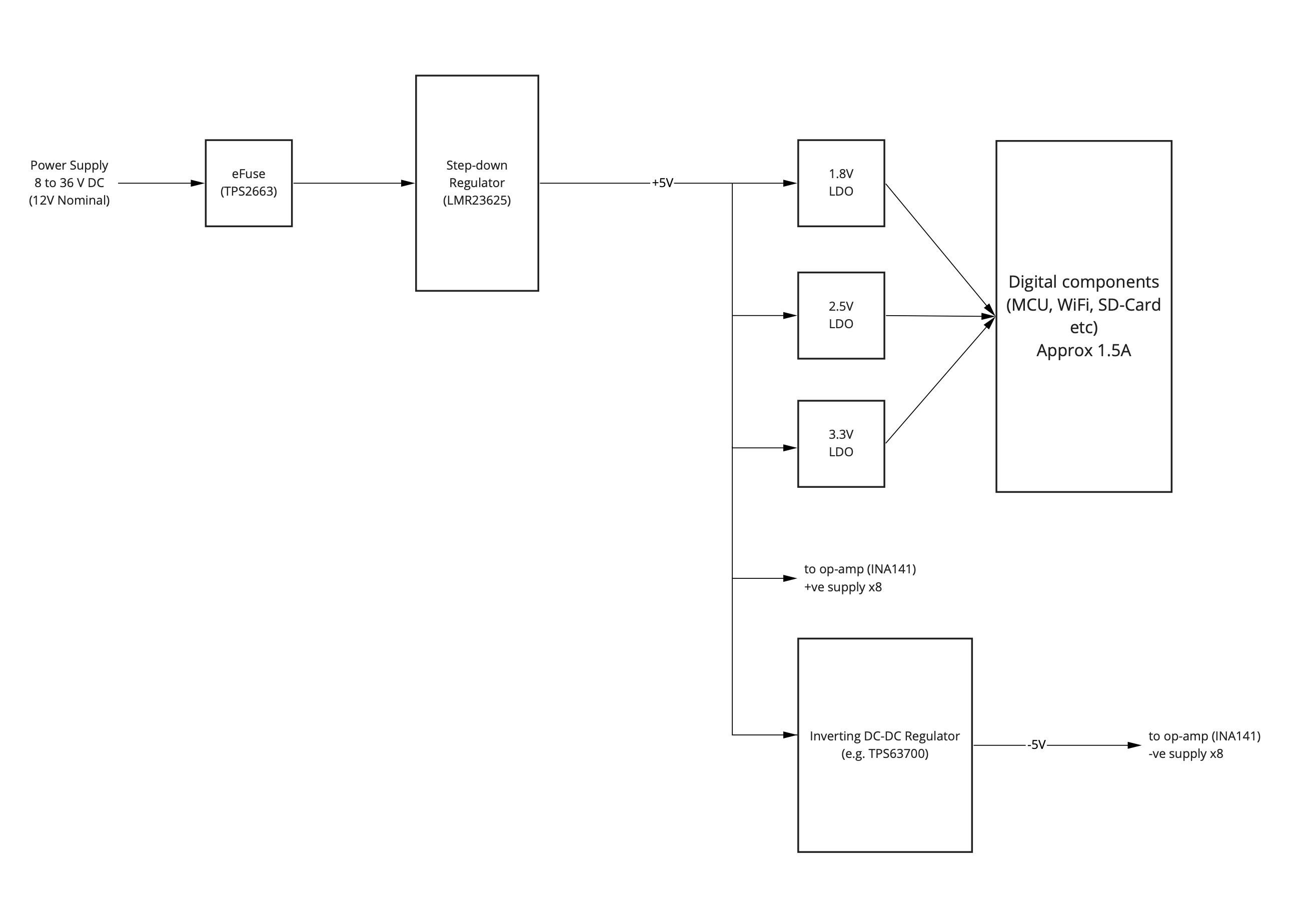
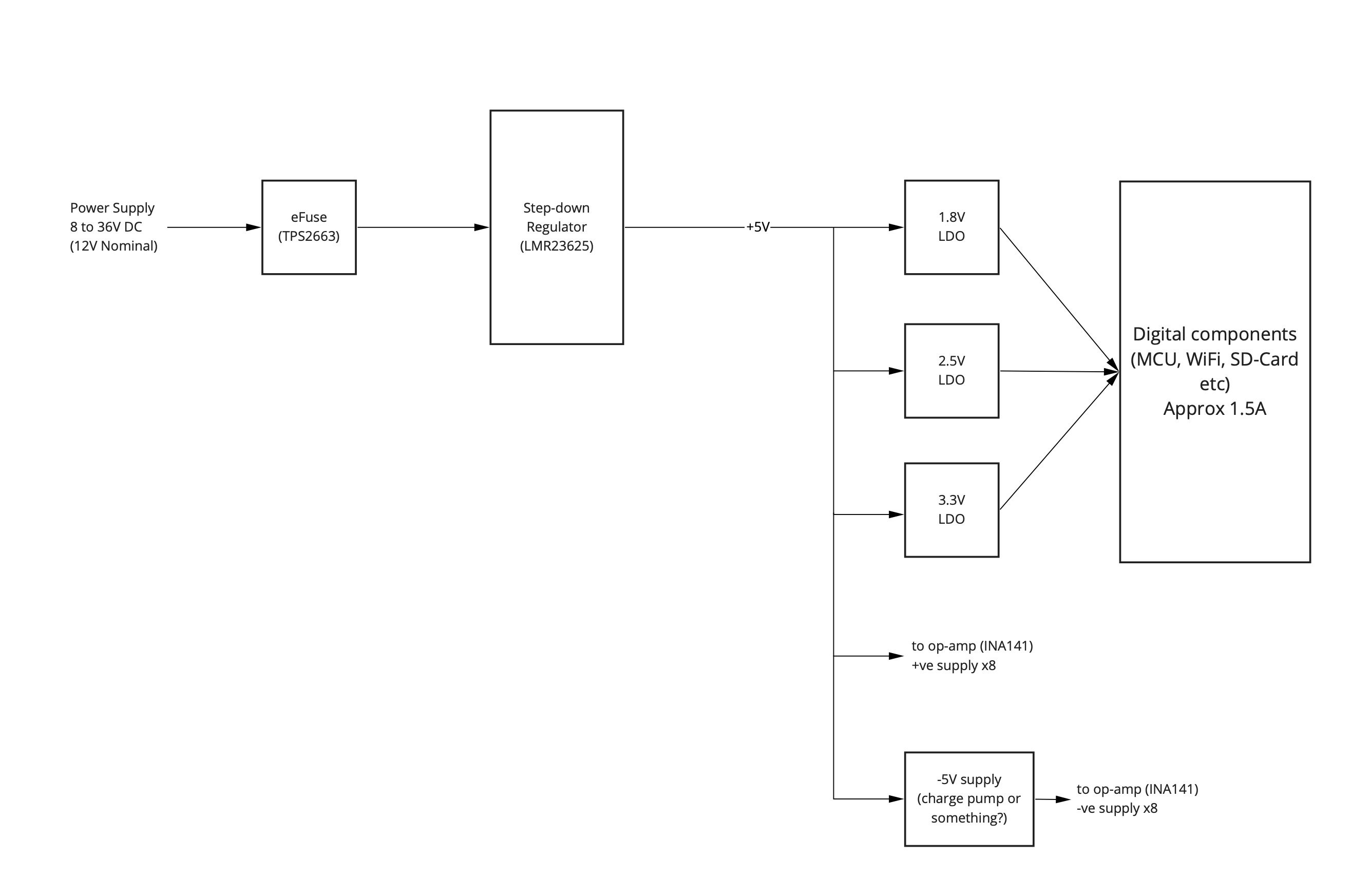
I'm designing a board that can take an input DC supply of between +8 and +36V DC (+12V nominally) and needs rails of +5V, +3.3V, +2.5V and +1.8V. My current design uses a step-down regulator (LMR23625) to generate the +5V and I use LDOs to generate the rest. This all works fine. This block diagram illustrates it:
The problem is that I also have an analog section to the board (8x INA141 instrumentation amplifiers and an 8 channel ADC). The INA141s need a negative supply rail of -5V. What is the best way for me to generate the -5V? I was thinking about daisy-chaining the TPS63700 off the LMR23635, e.g.:

Is this a good idea or should I consider something like a dual-supply/split-rail regulator in place of the LMR23625?
I'm not constrained for PCB space. The board is 200x60 mm (4 layer, double sided) and I can dedicate a good 3rd of that to power supplies. The overall system current is maximum 2.5A (nominally lower).
The worst case current requirement of the -5V rail 80 mA, maybe 100 mA to be safe (10mA per INA141 x 8 + some head-room). Nominal value is about 3 mA each.

