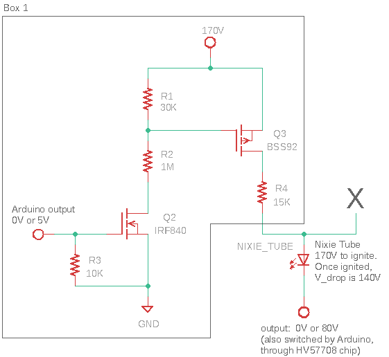
I am designing a circuit that enables using an Arduino board to drive Nixie tubes (https://en.wikipedia.org/wiki/Nixie_tube), which are LED-like devices that require ~170V to ignite, and ~140V to maintain after ignition. A resistor in series is used to limit the current to 1-5 mA.
In order to individually control the 10 digits in the tube, I use a common solution, a high-voltage (80V) register (HV57708) that connects to each of the 10 cathode pins of the tube, so I can programmatically switch each digit (by switching between 0V and 80V, the voltage drop is either 170V or 90V across any single digit, which corresponds to the on and off states of that digit).
However, this type of control does not allow me to change the brightness of the tubes, which needs to be modulated either by varying the current, or by PWM. (Changing input voltage is not a recommended solution to adjusting the tube brightness, as it affects evenness of the glow.) The low-side switch, mediated by HV57708, could only support software PWM, which would take up all resources of the Arduino processor. (i.e. The entire processor has to be dedicated to this software PWM task, which is not ideal for my application.)
Therefore, I would like to implement an additional high-side switch, which would be connected to the single anode pin of the tube (and would thus switch on or off the entire tube, across all digits, which is a behavior that I aim for).
=================================================================
I have fairly little experience with circuit design, but after ~1 week of research, have come to the following design (see attached image). I would like to ask whether a few questions about this circuit:
(1) From the experienced eyes, would this circuit work (a) safely and reliably, and (b) achieve the intended switching behavior?
To explain this circuit:
-- Q3 is a p-channel power MOSFET; Q2 is a n-channel power MOSFET that drives Q3. (Otherwise, the 5V from Arduino cannot drive the 170V supply voltage).
-- R1 and R2 are a voltage divider to drop the voltage to ~165V when Q2 is turned on (when Arduino outputs 5V). This 5V difference turns Q3 on. (The limit on V_GS of Q3 is +/- 20V. So it seems necessary to have this voltage divider, instead of just throwing the full 170V on V_GS) The high resistance values were selected to keep the ON-state current low, because R2 drops ~165V and so the dissipated power could easily get above SMD resistor power ratings (~100 mW) even at a current of ~1 mA.
-- R3 is a pull-down resistor to ensure that the pin is never floating. I pick 10K (on-state current of 0.5 mA) for no strong reason; please suggest if other values could work better.
-- The output pin at the bottom is from HV57708, which connects to all 10 cathode pins from the Nixie tube. Typically, 9 out of the 10 would be set to 80V (an off-state, because even if the top-side switch is ON, 170V - 80V = 90V is not sufficient to ignite the tube), whereas 1 out of the 10 would be set to 0V (an on state; only applied to the cathode corresponding to the digit that we intend to glow).
-- Regard X as an open-circuit (nothing attached) for now.
(2) Would this high-side switch be able to support PWM-based brightness control, if the "Arduino output" pin is a PWM-compatible pin on Arduino?
(3) Let us now say that we want to completely avoid using PWM, which could have benefits, as some hypothesized that it reduces tube life. In such case, to achieve adjustments of the tube brightness, it seems like a plausible approach is to duplicate and mirror the entire Box 1, and place it at the location marked "X", again connected through R4. Under such scheme, the Arduino could control the number (and which) of the current-limiting resistors (R4's) that are in parallel.
More parallel resistors would increase the total current from the 170V source, thus brightening the tube -- correct? For example, with just 2 of these circuits, one with R4_A = 15K and one with R4_B = 30K, three different ON-state brightness levels could be produced. ( I = (170V-140V)/ R_equivalent, where R_equivalent is either 15K, 30K, or 1/(1/15+1/30) = 10K, leading to I = 3mA, 2mA or 1mA. This seems sufficient for my purpose. Would this type of stacking strategy work?
(4) If any expert have other solutions or insights on how to implement this tube brightness adjustment, I will be very curious to hear. (I initially thought about using a single digital potentiometer; i.e. 170V connects to R4, then to digi-POT, then to Nixie tube, then to HV57708 output. However, existing digi-POTs seems to have low current rating (~5 mA, which is about the current that needs to pass through) and low tolerated voltage drop (< 30 V).)

