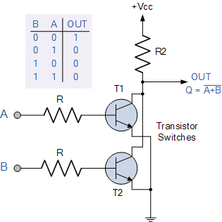
It looks like you have a NOR gate now, albeit non-standard RTL input levels. TTL is two diode drops and HCMOS is Vcc/2 threshold.
The saturated gain of a transistor is only 10 to 20. So choose R values for a gain of 10 for reliable current switching.
CMOS NOR Gate
This is a simplified CMOS NOR gate with fancy triangular inputs running at 100 & 110 Hz to give a 10 Hz beat frequency on the output. Purpose is to show the linear input threshold. This uses n and p Mosfets to give low impedance for both output states, although the high side usually has a resistor to current limit it.


OUTterminal of the gate, and when one of the inputs (let's sayA) is HIGH (so from the truth table, OUT should be LOW), the LED glows brighter, and the other one works just fine? What is the 'other one', and what would 'fine' behaviour be for you? \$\endgroup\$