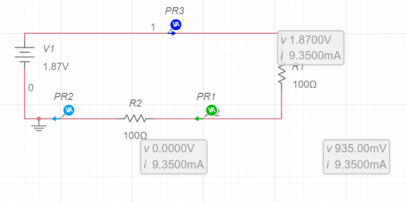
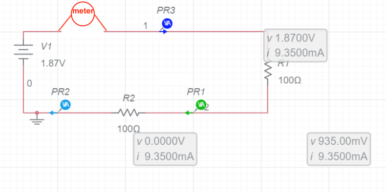
Now when I measure current across the first and the second resistor individually I get around 20mA
That is correct, because (as highlighted in a comment by jsotola) each time you try to measure current "across" an individual resistor, using a multimeter set to one of its current ranges, you are shorting out that resistor, using the current shunt in the multimeter (see the link I include below).
Therefore for each of those two measurements, the only resistor still in circuit is the other 100 Ω resistor (since the resistor you are measuring "across" is shorted out, as I described) and so the nominal current is:
1.87 V [battery voltage] / 100 ohms [the resistance of the other resistor] = 18.7 mA
(assuming those exact values for V and R which you gave, for the battery voltage and resistor)
That is why you are measuring approximately 20 mA.
It probably does not match Ohm's law due to error of measurement.
No, the measured value (20 mA) does approximately match Ohm's law. It is your expected current value (9.35 mA shown in the schematic) which is wrong for your actual test. That is because that value assumes the current is being measured correctly, and that both 100 Ω are in-circuit (1.87 V / (100 Ω + 100 Ω) = 9.35 mA).
Whereas in your actual test, one of the resistors is being shorted out when you measure the current "across" that resistor. That leads to an actual measured current being twice the value you expected (half the resistance leads to twice the current, with the same voltage).
See my answer here explaining a very similar mistake by someone else.
Don't try to measure the current "across" both resistors, as then you are shorting out both of them, so neither of them is limiting the current from the battery, and the only limit becomes things like the internal resistance of the battery and the wiring. It is easy to damage your multimeter, or blow its internal fuse on that current range (if it has one), or even have the meter explode and hurt you (for high-energy measurements), if you try to measure current "across" a source which is able to supply lots of power e.g. a mains socket.
If you are using a multimeter on its current range, it must be in series with the circuit whose current you are trying to measure (you are using it in parallel - that is the mistake). Again, see the link above.


througha resistor .... voltage developsacrossa resistor ... you have to break the circuit and insert the ammeter \$\endgroup\$