0
\$\begingroup\$

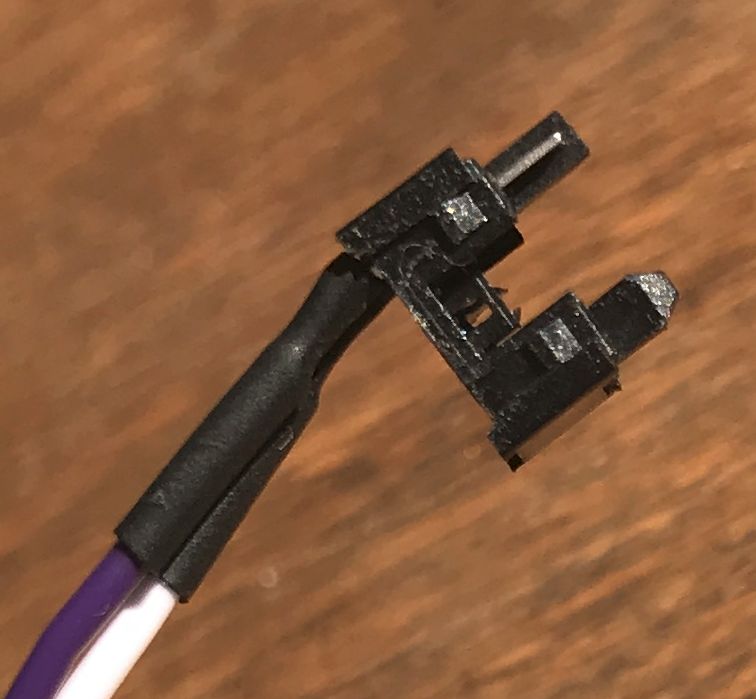
I have this momentary switch that is used as a Reset switch on my computer : enter image description here
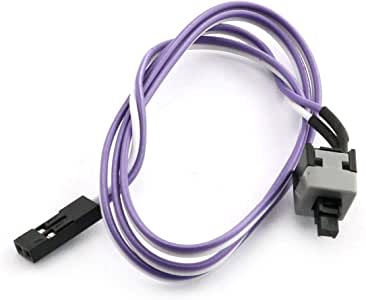
I opened it and I'd like to assemble it back.

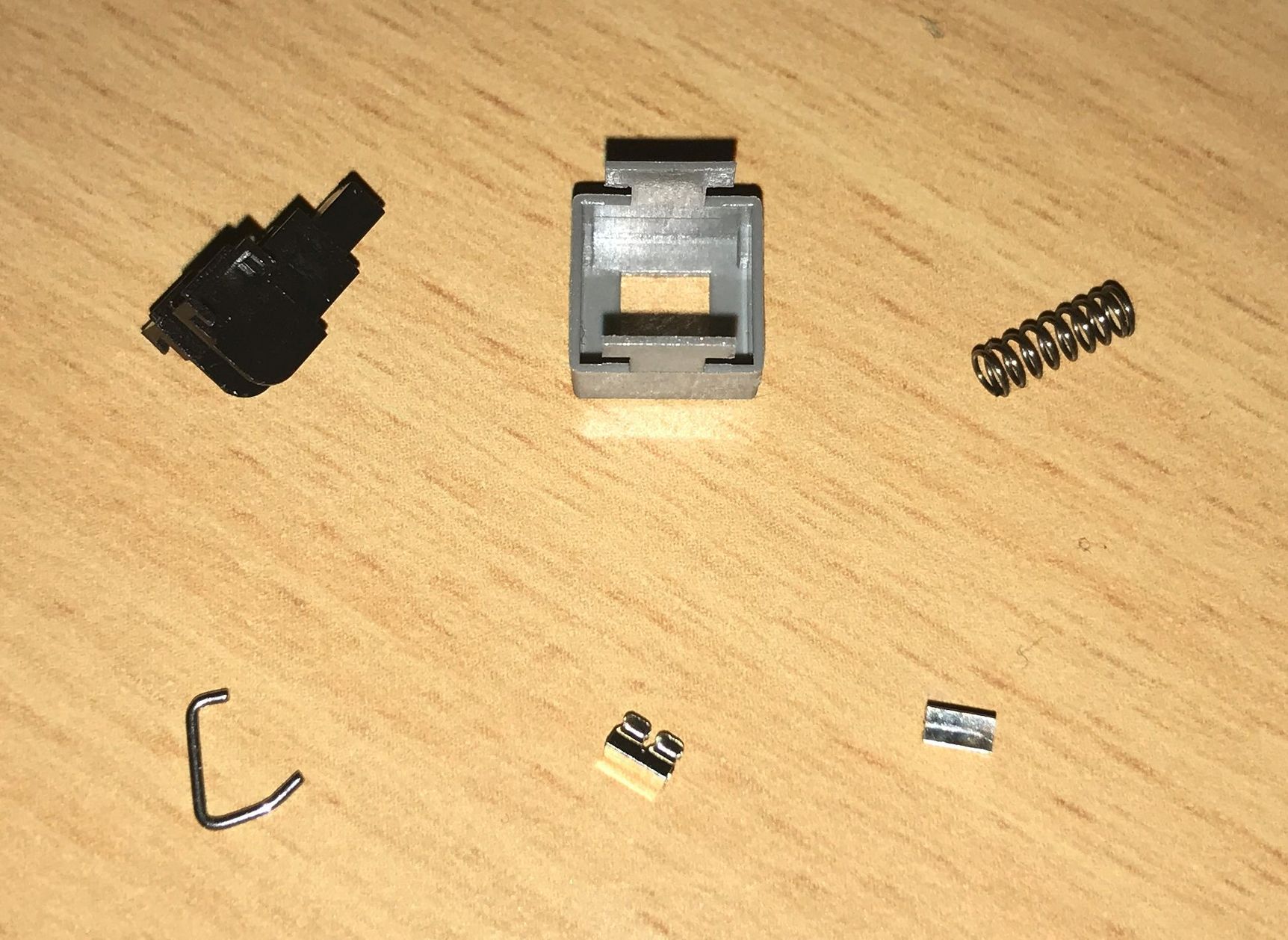
It's made with these parts:

  • the push button
  • the grey "frame"
  • a spring
  • a hard "wire" in J-shape
  • 2 small "clamp clips" that are, let's say "rectangular"
  • the black base connected to the cable

The problem is that I can't find any schematic on how this switch is assembled to be able to reassemble it. Can you help me?

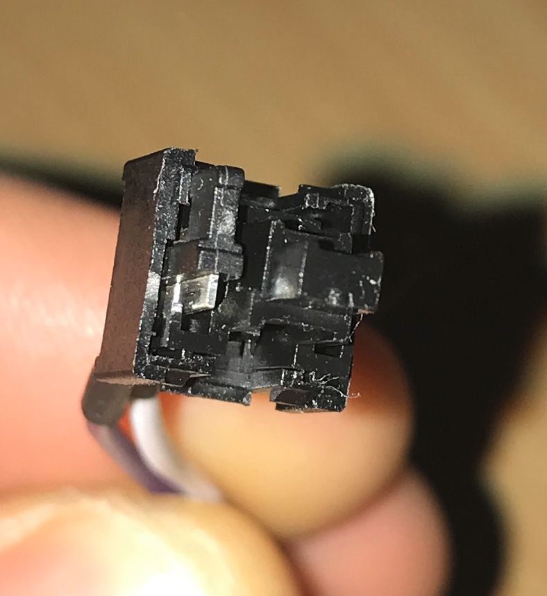
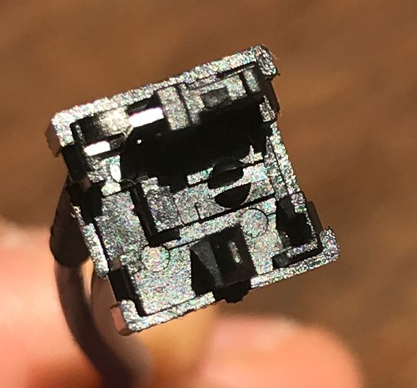
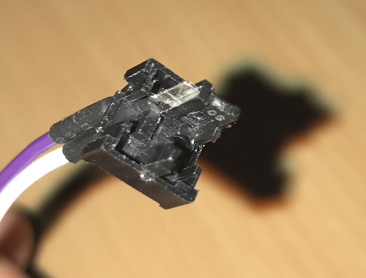
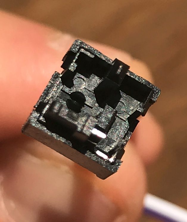
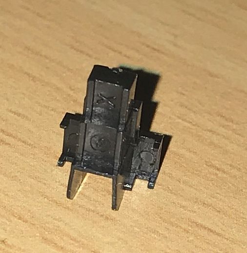
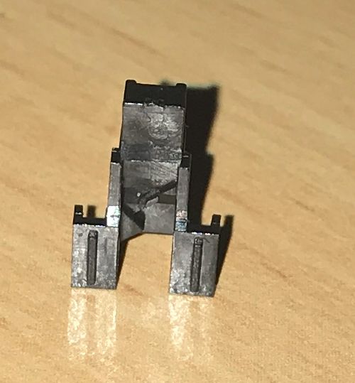
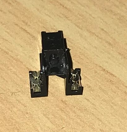
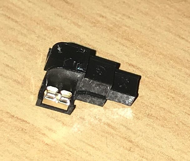
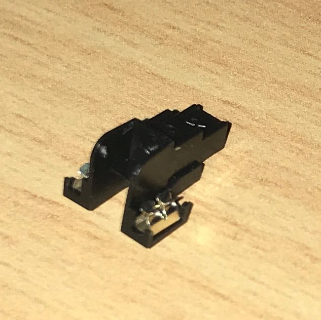
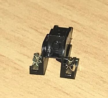
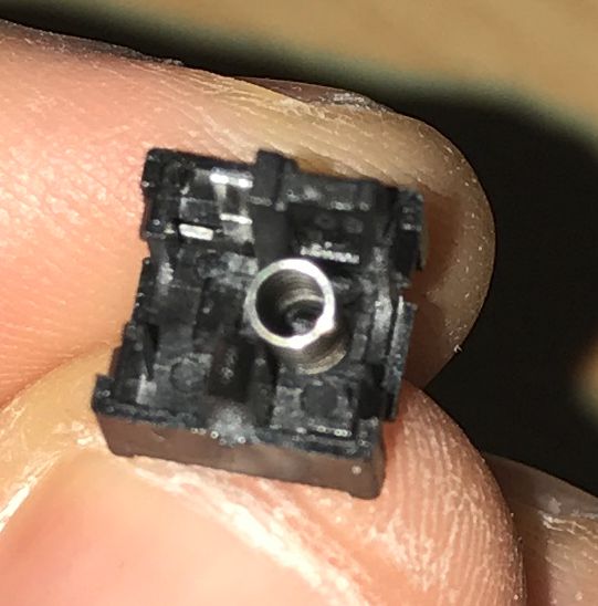
I suppose that the spring goes on the "rounded" splitted plastic pin on the base (even the pin seems to be a bit large for the spring diameter, and the 2 "clamp clips" seems to go on perfectly dimensionned places on each side of the button, sliding straight down on the metal part connected to the wire when the button is pushed (but only one of these "extruded" metal parts is clearly visible).

enter image description here enter image description here enter image description here enter image description here enter image description here enter image description here enter image description here

With the button mounted on the base : With button mounted With button mounted
EDIT 2020.04.14

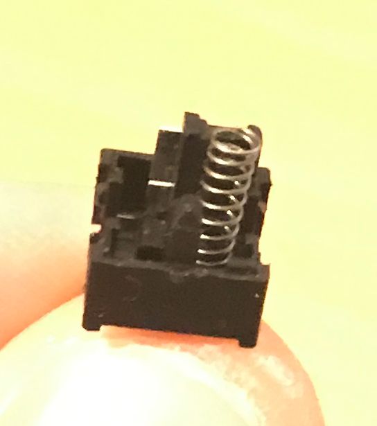
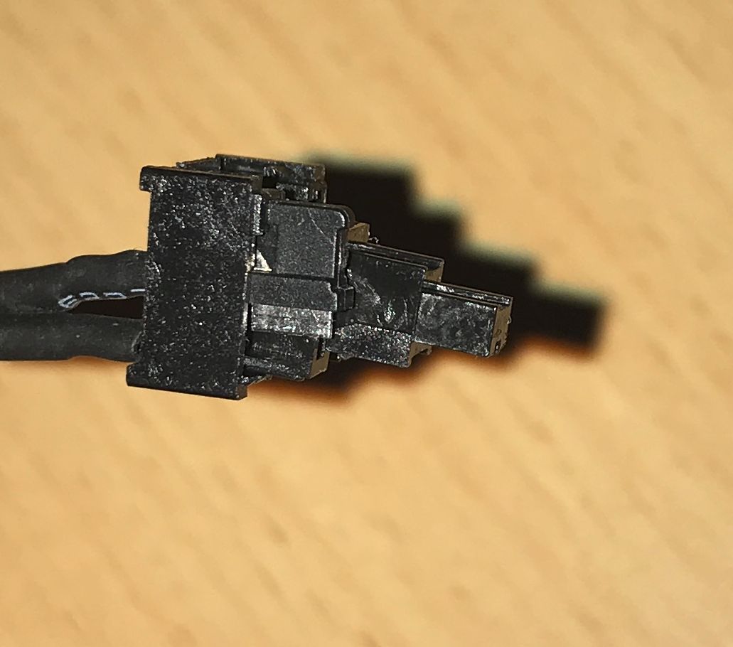
Here are some pictures of how I suppose the things go together.
But saying that, I don't see the point of putting the 2 small clamps on each side of the button, as there is one of them that contact nothing else than plastic. And I suppose that the other one, that slides on the visible metal part connected to one wire, cannot contact anything as the second metal part is almost (if not totally) flush with the plastic bottom, and more there is a tiny plastic part under the clamp, to hold it into the button, that should avoid any possible contact.

enter image description here enter image description here enter image description here enter image description here enter image description here enter image description here enter image description here enter image description here

\$\endgroup\$
0

1 Answer 1

1
\$\begingroup\$

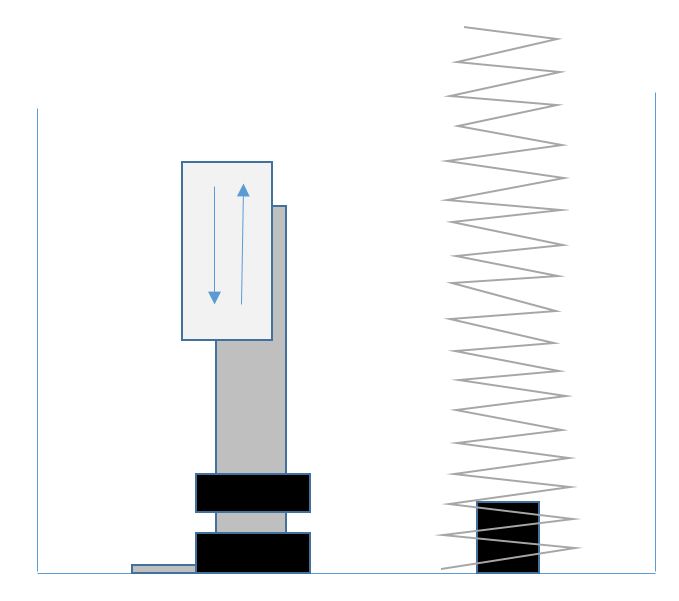
The clips slide on the metal part in the base to control the flow of electricity, they somehow fit into the moving part of the button,

the spring goes inside the bottom of the moving part.

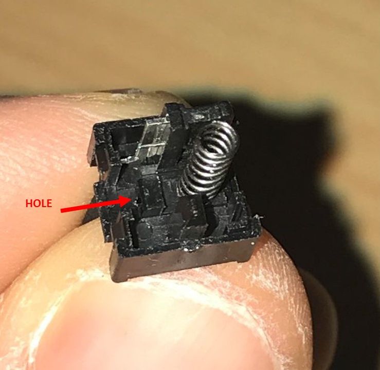
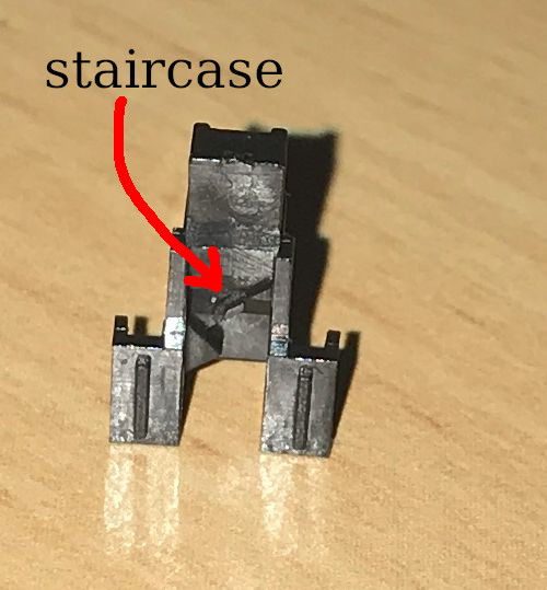
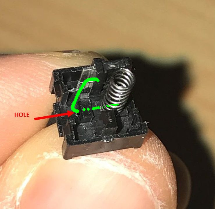
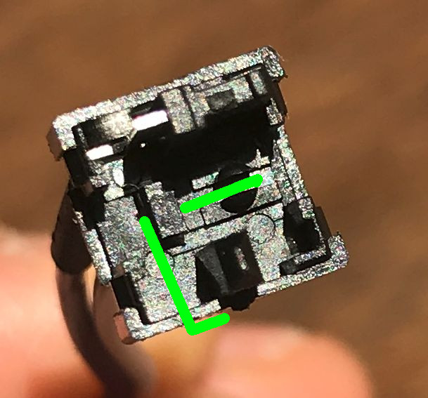
the J shape goes under the moving part and the spring and hooks back onto the slopy staircase part of the moving part with its short end. the long end hooks into the hole and goes under the spring.

the grey frame holds everything together.

"staircase" enter image description here

hook position

enter image description here enter image description here

\$\endgroup\$
7
  • \$\begingroup\$ I think I figured it out for the clamps, at least for one of them. OK for the spring. But I don't understand what you mean for the J shape part. I updated the question with more pictures at this stage, is this what you meant ? \$\endgroup\$
    – Oliver
    Commented Apr 14, 2020 at 17:19
  • \$\begingroup\$ thanks for the photos. \$\endgroup\$ Commented Apr 14, 2020 at 21:32
  • \$\begingroup\$ Thank you ! I tried this after your previous explanations, but it didn't work (no grip on the button). But... when I tried, the small leg of the wire was into the hole of the spring. Does it go there, or do I have to put it after the spring ? \$\endgroup\$
    – Oliver
    Commented Apr 14, 2020 at 23:30
  • \$\begingroup\$ Waiting for you answer, I tried mouting it as said just before (short leg after the spring, near the border, and long leg on the button's stairs). That's ok, but I don't have the click sound when pushing the button, as if it was not there. \$\endgroup\$
    – Oliver
    Commented Apr 14, 2020 at 23:42
  • \$\begingroup\$ I rthink the long leg goes under the spring between the halves of the mound \$\endgroup\$ Commented Apr 15, 2020 at 3:13

Your Answer

By clicking “Post Your Answer”, you agree to our terms of service and acknowledge you have read our privacy policy.

Not the answer you're looking for? Browse other questions tagged or ask your own question.