1
\$\begingroup\$

The Ebers-Moll equation is given by:$$I_C = I_S(T) * (e^{V_{BE}/V_T})$$ where \$V_T\$ = \$kT/q\$ = 25.3mV at room temperature. In TAOE (2.3.1), it mentioned

\$I_S(T)\$ is the saturation current of the particular transistor (which depends strongly on temperature, T ... \$I_S(T)\$ approximates the reverse leakage current (roughly \$10^{-15}\$A for a small signal transistor like the 2N3904.

I ran a simple simulation just to test the Ebers-Moll equation, where \$I_C\$ is just approximated to \$10^{-15}\$A, and taking \$V_{BE}\$'s value directly from the simulation: $$I_C = 10^{-15} * e^{0.727330 \div 0.0253} = 0.003A \ \ or \ \ 3mA$$

The value is over two orders to one simulated by the program iCircuit (427.267mA). If I just use KVL and multiply the default \$\beta\$ of 100, I get \$I_C = (5-0.727330) \ \div \ 1000 * \beta = 0.427262A \ \ or \ \ 427.267mA\$ matching that in the simulation. How am I supposed to use Ebers-Moll equation and why is it more accurate to determine collector current by base-to-emitter voltage. I just plug in some basic values in and the result did not even turn out close.

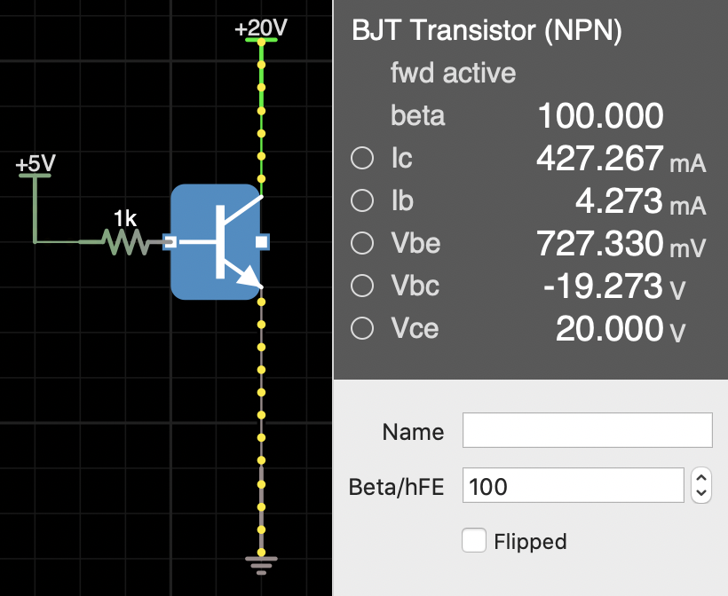
BJT simulation

\$\endgroup\$
14
  • 1
    \$\begingroup\$ The solution must start with solving for the base current. There are a number of effects not accounted in your model, which is a level 1 Ebers-Moll and doesn't include level 3 effects (such as the Early Effect, not terribly important here) nor the emission co-efficient, to start. But you are really making a huge mistake by using a simulator's VBE value for the formula. You don't fully understand the model used in simulation, and then you apply a different model in your calculations. There's no way that will work out for you. \$\endgroup\$
    – jonk
    Commented Apr 20, 2020 at 5:12
  • 1
    \$\begingroup\$ You want to solve: \$5\:\text{V}-1\:\text{k}\Omega\cdot I_\text{B} - V_T\,\ln\left(1+\frac{\beta \,I_\text{B}}{I_\text{SAT}}\right)=0\:\text{V}\$ for \$I_\text{B}\$. Once you have that, you can compute \$I_\text{C}=\beta\,I_\text{B}\$. Once you have that, you can work out \$V_\text{BE}=V_T\,\ln\left(1+\frac{I_\text{C}}{I_\text{SAT}}\right)\$. Those calculations will be consistent with the model you have. The simulator is using a different \$I_\text{SAT}\$ and probably a different \$V_T\$ and, as a result, you are getting confused. There are 2nd order effects. But they don't explain two orders. \$\endgroup\$
    – jonk
    Commented Apr 20, 2020 at 5:48
  • 1
    \$\begingroup\$ I also find, then, that \$V_\text{BE}\approx 851.571\:\text{mV}\$. Which, you may note, is about a \$124\:\text{mV}\$ difference. And with 10 times the collector current for each \$60\:\text{mV}\$ difference, that just about completely explains the two orders of magnitude you found. \$\endgroup\$
    – jonk
    Commented Apr 20, 2020 at 6:34
  • 1
    \$\begingroup\$ Here are the Ebers-Moll equations (level 1, as they do not include junction capacitance or the Early Effect [base-width modulation.]) I wrote these down here, some time back. There are three entirely equivalent versions and I provide all three. But jump to the non-linear hybrid-\$\pi\$ version. You will see the beta factors there. They are not derived from some theoretical model. They are supplied into the model. They are required. \$\endgroup\$
    – jonk
    Commented Apr 20, 2020 at 6:56
  • 1
    \$\begingroup\$ It's true, though, that you do not want to depend too highly on their values. That said, you can and must rely on some range. You can use sensitivity equations to work out a reasoned range of behavior vs any particular parameter variation. And with these, you can work out an "optimal" operating point given some inputs. For example, the operating temperature of the device may vary over some known range. And the beta value for a specific family of devices may be guaranteed to be no less than some particular value when operating at some temperature and collector current. Etc. \$\endgroup\$
    – jonk
    Commented Apr 20, 2020 at 6:58

2 Answers 2

1
\$\begingroup\$

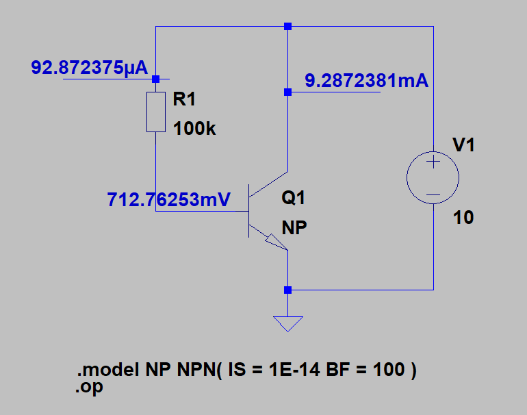
Let me examine this simple circuit

enter image description here

We know that for an ideal BJT the collector current will follow this equation:

$$I_C = I_S \times \left(e^{\frac{V_{BE}}{V_T}}-1 \right)$$

As you can see in this case we have \$I_S = 1E-14 = 10\text{fA}\$ and by default the ambient temperature is equal to \$ 27°C\$ thus \$V_T = 25.8649\text{mV}\$ and \$\beta = 100\$. And the emission coefficient/ideality factor \$NF = 1\$ by default.

And we can try to solve this circuit using the old method known as an iterative method.

First, we as usually assume some \$V_{BE}\$ value and solve for \$I_B\$ current.

$$I_B(1) = \frac{10V - 0.6V}{100k\Omega} = 94\mu A$$

Now I will use this equation to solve for the new \$V_{BE}\$ value.

$$ V_{BE} = V_T \ln \left(\frac{I_C}{I_S}+1\right)$$

But because you want to find the base current we must modify the equation to:

$$I_{SB} = \frac{I_S}{\beta} = 1E-16 = 0.1\text{fA}$$

$$ V_{BE} = V_T \ln \left(\frac{I_B}{I_{SB}}+1\right)$$

So, we finally can find the new \$V_{BE}\$

$$ V_{BE}(2) = V_T \ln \left(\frac{I_B}{I_{SB}}+1\right) = 0.7131V$$

Now I will use this new \$V_{BE}\$ value to find the new base current value.

$$ I_B(2) = \frac{10V - 0.7131V}{100k\Omega} = 92.869 \mu A$$

And we continue and find new \$V_{BE}\$ value and base current value.

$$ V_{BE}(3) = 25.8649\text{mV} \ln \left(\frac{ 92.869 \mu A}{0.1\text{fA}}+1\right) = 0.71276V$$

$$ I_B(3) = \frac{10V - 0.7128V}{100k\Omega} = 92.872 \mu A$$

$$ V_{BE}(4) = 25.8649\text{mV} \ln \left(\frac{ 92.872 \mu A}{0.1\text{fA}}+1\right) = 0.71276V$$

AS you can see because we are getting almost the same numbers we can conclude that.

\$V_{BE} = 0.7128V\$ and \$I_B = 92.872 \mu A\$ and \$I_C = \beta I_B = 9.2872mA\$

Of course, sometimes the equation does not converge, then we need to use for example the average value of the previous estimate and the calculated value.

\$\endgroup\$
1
\$\begingroup\$

You are supplying 5V on the 1k resistor will give a base current of about 4.273mA. However you say you should get 3mA as the collector current. However this would violate the idea that the current gain is 100.

If beta is truly 100 then the base current should be 30uA to give a collector current of 3mA when Vbe is 727mV. I suggest changing either the base resistor or voltage at end of base resistor to give a base current of 30uA and see if things improve.

\$\endgroup\$
1
  • \$\begingroup\$ Comments are not for extended discussion; this conversation has been moved to chat. \$\endgroup\$
    – Voltage Spike
    Commented Jun 8, 2020 at 22:36

Your Answer

By clicking “Post Your Answer”, you agree to our terms of service and acknowledge you have read our privacy policy.

Not the answer you're looking for? Browse other questions tagged or ask your own question.