18
\$\begingroup\$

Despite searching I can't seem to find the answer to this. In understanding harmonic distortion, one piece of the puzzle that is missing for me is: - why does the distortion manifest at harmonic frequencies and not other frequencies.

Feel free to simply point me at a textbook / reading that explains it, if that's easier!

  • I understand that non-linear loads can create distortion. Intuitively, this is because the load can change it's characteristics (resistance, capacitance, etc etc.) in complex (difficult to predict...) fashion.
  • I understand enough of Fourier analysis to understand harmonics, 1st (fundamental), 2nd, etc etc.
  • I don't see why the distortion would tend to be at harmonic frequencies.

E.g., if I put a 1KHz sine wave through a non-linear load, why would the distortion show up at harmonics and not something a little less friendly, say, at 1.8KHz, depending on the circuit design?

I come across this in studying audio systems. They rely on THD as a measure of fidelity (for non-clipping signals), but it baffles me why the distortion falls into nicely behaved harmonics...

Thanks!!


Update: thanks to all the great quick answers below, I think I figured it out.

  • non-linear loads are still predicable: "A nonlinear impedance effects every cycle of the waveform in the same way" (Charles Cowie)

  • other impacts that do not effect every cycle the same way are transient, or interharmonic. These can be highly unpredictable, due to external forces, etc. They can change the fundamental frequency (e.g., a sharp cutoff)

  • any periodic (distorted?) waveform "can be represented by their fundamental component and a Fourier series of harmonics of various magnitudes, frequencies and angles.(this cites another source)" (from relayman357)

  • there are some great math workthroughs below that illustrate this.

So the piece that I was missing was that the distorted waveform still sits on the fundamental frequency in a periodic fashion, so by definition the distortions are harmonics (different phases/amplitudes,etc.).

Non harmonic distortion (interharmonic) isn't periodic.

Loads like amplifiers don't typically change the fundamental frequency but "give it hair", so it's still periodic.

\$\endgroup\$
5
  • 2
    \$\begingroup\$ Try and think of a non-linearity load that would produce 1.8 kHz when the input is a sine of 1 kHz. I'd be happy to see one. \$\endgroup\$
    – Andy aka
    Commented Apr 22, 2020 at 14:28
  • 1
    \$\begingroup\$ Thanks. This may be a sign of my lack of EE knowledge, as I'm from the CS world. I could imagine a microcontroller setup to work and perturb the signal at just the right (wrong?) interval. Perhaps I'm crossing wires between distortion and signal generation, but one just seems like a purposeful version of the other? \$\endgroup\$
    – jyoung999
    Commented Apr 22, 2020 at 14:34
  • 1
    \$\begingroup\$ Well, do a Fourier analysis on a 1.8 kHz sinewave that is abruptly reset back to its starting point every millisecond and see how it pans out. \$\endgroup\$
    – Andy aka
    Commented Apr 22, 2020 at 14:36
  • 3
    \$\begingroup\$ Here’s a good read about inter-harmonics. \$\endgroup\$ Commented Apr 22, 2020 at 14:38
  • \$\begingroup\$ Note that no periodic signal has interharmonics, only harmonics (+ fundamental and DC offset), provided you correctly chose the period/frequency of the signal and correctly computed the Fourier coefficients/harmonics, so they're misleading in that sense. If a signal has inter-harmonics, it may not be periodic at all! In which case, for frequency spectrum, it should be represented by a Fourier transform, not a Fourier series. \$\endgroup\$
    – alejnavab
    Commented Mar 16, 2022 at 16:45

9 Answers 9

25
\$\begingroup\$

A sinewave of 1 kHz only contains one frequency: 1 kHz. Let's describe that mathematically:

\$x = sin(2 \pi f t) \$

Where \$f\$ is the 1 kHz, \$t\$ equals time and \$X\$ is the sinusoidal signal.

If an amplifier is ideal then it would only amplify the signal, i.e. increase the amplitude:

\$y = A x = A sin(2 \pi f t)\$

Note how that still has is just a sinewave, only the amplitude (value of the minimums and maximums) have changed.

But that's a linear amplifier, it will not introduce harmonics.

Now what if the amplifier distorts.

Do you remember the Taylor series? It is a way to express any function in the form of a polynomial like this:

\$y = A x + B x^2 + C x^3 ...\$

What I wrote there is the Taylor expansion that describes the behavior of an amplifier with distortion.

If you fill in \$x = sin(2 \pi f t) \$ you will get \$sin(2 \pi f t) \$, \$x = sin^2(2 \pi f t) \$ and \$x = sin^3(2 \pi f t) \$ terms and these are the harmonic frequencies.

Note that there is no way to get terms other than \$x = sin^n(2 \pi f t) \$ making it impossible to get frequencies that are not a multiple of the base frequency of \$x\$.

Bonus question:

What would be needed to get other (non-harmonic) frequencies?

With a sinewave as input, there is no way. But if we combine two or more sinewaves of different frequencies, then we can get intermodulation products. For example, make \$x\$ a signal consisting of a 1 kHz (\$f_1\$) and a 200 Hz (\$f_2\$) tone:

\$x = sin(2 \pi f_1 t) + sin(2 \pi f_2 t)\$

Then at the output of a distorting amplifier we will find sum and difference frequencies so we would get:

  • 200 Hz
  • 400 Hz ( 2 x 200 Hz, the 2nd harmonic of \$f_2\$)
  • 600 Hz ( 3 x 200 Hz, the 3rd harmonic of \$f_2\$)
  • 800 Hz (1 kHz - 200 Hz)
  • 1 kHz
  • 1.2 kHz ( 1 kHz + 200 Hz)
  • 1.4 kHz ( 1 kHz + 2 x 200 Hz)
  • etc etc

note how they're all 200 Hz (\$f_2\$) apart!

How many frequency components are present depends on how much the amplifier distorts and the amplitudes of the signals.

\$\endgroup\$
7
  • \$\begingroup\$ Awesome. I haven't seen the Taylor series in many years, but this ties in with the other answers very nicely. Thanks. \$\endgroup\$
    – jyoung999
    Commented Apr 22, 2020 at 15:17
  • 2
    \$\begingroup\$ @jyoung999 My pleasure, may I draw your attention to the bonus question (and answer, no worries :-) ) I added. This also relates to audio equipment as THD doesn't tell us everything, my guess is that our ears are not so sensitive to Harmonics of single tones but very sensitive to intermodulation products! \$\endgroup\$ Commented Apr 23, 2020 at 8:26
  • 2
    \$\begingroup\$ This seems to show that the intermodulation products are all harmonics of one of the inputs. Perhaps 1 kHz and 300 Hz inputs would be a better example, showing sum and difference frequencies that are not harmonics of either input? \$\endgroup\$
    – davidcary
    Commented Apr 23, 2020 at 14:52
  • \$\begingroup\$ @Bimpelrekkie What do you mean in the bold text when you said "What would be needed to get other (non-harmonic) frequencies?"? The (fundamental) frequency of the given input signal, \$x(t)= \sin {(2π \cdot 1 \text{ kHz} \cdot t)} + \sin {(2π \cdot 200 \text{ Hz} \cdot t)}\$, is 200 Hz. If output signal is periodic but its (fundamental) frequency isn't 200 Hz, it just means the device is non-linear, however the output signal can still be decomposed into harmonics (integer frequency of the fundamental output.) \$\endgroup\$
    – alejnavab
    Commented Sep 23, 2020 at 21:04
  • \$\begingroup\$ @AlejandroNava Maybe you're confused about the actual fundamental frequency? For a 1 kHz + 200 Hz signal, the waveform repeats every 1/ 200 Hz = 5 ms. 20 Hz is the fundamental and 1 kHz is the 5th harmonic: 5x 200 Hz = 1 kHz. The same still applies if you mix 1 kHz and 201 Hz, but then the repetition period of the signal gets much longer. You need a fundamental of only 1 Hz: 1000x 1 Hz = 1 kHz and 201x 1 Hz = 201 Hz. That means the fundamental frequency for such a signal is 1 Hz. \$\endgroup\$ Commented Sep 24, 2020 at 8:12
10
\$\begingroup\$

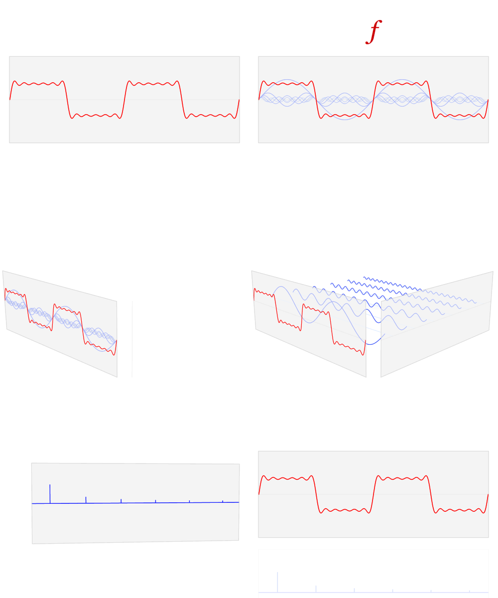
Fourier was saying that any periodic wave can be made up of the fundamental and its harmonics in various ratios.

enter image description here

Figure 1. This fabulous illustration of the Fourier Transform by Lucas V. Barbosa on Wikipedia's Fourier transform page shows the transformation of a periodic waveform from the time domain to the frequency domain. The frequency plot shows the relative strength of the harmonics with clarity that could not be obtained from staring at the time plot.

  • It should be apparent that the more square the time domain waveform is then the more harmonics you will have and these should be visible in the frequency domain.

I come across this in studying audio systems. They rely on THD as a measure of fidelity (for non-clipping signals), but it baffles me why the distortion falls into nicely behaved harmonics ...

If the harmonics are not integral multiples of the fundamental then, by definition they are not harmonics. If you mixed your fundamental f with an f × 1.8 as in your example then they would beat and only come into phase every five cycles of the fundamental (and nine cycles of the 'harmonic'). The result would be a different waveform with a new fundamental of f/5.

enter image description here

Figure 2. Fundamental (blue), fundamental × 1.8 (orange) and the sum (red).

\$\endgroup\$
2
  • 1
    \$\begingroup\$ Thanks - the missing piece to me was that the distortion in amplifiers also tends to be periodic along with the fundamental frequency. Once I got that, then the rest falls into line. Nice illustration. \$\endgroup\$
    – jyoung999
    Commented Apr 22, 2020 at 15:22
  • \$\begingroup\$ Good. Don't forget to accept an answer if your problem is solved. \$\endgroup\$
    – Transistor
    Commented Apr 22, 2020 at 15:51
7
\$\begingroup\$

A very large proportion of electronic circuits (including audio) belongs to the category of "time-invariant circuits" (linear circuit or not).

To give a idea of what are other circuits, logically called "time-variant circuits", it suffices to realize that they need to have some kind of clock, for example an internal oscillator (which could be a Larsen effect, or some auto-generated thermal noise) or external (50 Hz or 60 Hz hum). All "inert" (1) electric circuits are "time-invariant" because they are not "aware" of time (!).

Now, add the fact that the time response of a "time-invariant circuits" to a periodic signal is a also a periodic signal, and at the same frequency, add a little Mathematics "à la Fourier" and you see that distorsion can't be something else than harmonic.

(1) one could say "not alive"

\$\endgroup\$
1
  • 2
    \$\begingroup\$ After some thoughts, I realize that I should add a notion of "memory-less" to the term "time-invariant" - This is to exclude counters, that creates sub-harmonics \$\endgroup\$
    – andre314
    Commented Apr 22, 2020 at 17:45
6
\$\begingroup\$

That's because if you have a sinewave, say 1 kHz, it has only one frequency, and period of 1ms. If you distort it, it is not a pure sine wave any more, so it must have other frequencies. Since the distorted waveform periods are all identical, and they still happen periodically at 1ms, it would imply that the base frequency is still 1 kHz, and thus there are no components that are not somehow periodical to 1ms , so they must all have rate that fits integer multiple of whole sine periods to 1ms . If there was a say 1.8 kHz component present, that would make the signal period in time domain to not be 1ms any more, but something else. So the harmonics must only be integer multiples of the 1kHz.

\$\endgroup\$
4
\$\begingroup\$

Harmonic distortion is harmonic because it is related to the primary periodic waveform that is the basis for comparison. A nonlinear impedance effects every cycle of the waveform in the same way. It does not randomly insert something here and there. Distortion that is not harmonic is often transient. If something is switched on and off at random intervals and inserts some noise every time it is switched it is still considered to be transient. In audio circuits, a power frequency hum is not harmonic distortion, and is identified as a 50 Hz or 60 Hz hum. There are probably plenty of examples of EMI noise. All of those kinds of "distortion" are identified differently from harmonic distortion.

\$\endgroup\$
2
  • \$\begingroup\$ Awesome, thanks, I appreciate the vocab help. So those other sources of distortion just fall outside the harmonic discussion. I'll still need to read up on /why/ the harmonic distortion happens, then, e.g., in the case of an op amp circuit.. Your comment about "effects every cycle..in the same way" is helping with my intuition \$\endgroup\$
    – jyoung999
    Commented Apr 22, 2020 at 14:48
  • 1
    \$\begingroup\$ Be sure to look at the link provided by @relayman357> \$\endgroup\$
    – user80875
    Commented Apr 22, 2020 at 14:49
4
\$\begingroup\$

Consider a memory-less non-linear system as follows: $$y(t) = ax(t) +bx^2(t)$$ If you have an input signal \$x(t) = Asin(\omega t)\$, then output will be: $$y(t) = aAsin(\omega t) + bA^2sin^2(\omega t) = aAsin(\omega t) + \frac{bA^2}{2}(1-cos(2\omega t))$$ $$y(t) = \frac{bA^2}{2} + aAsin(\omega t) - \frac{bA^2}{2}cos(2\omega t)$$ Thus in the output you see the fundamental or the applied frequency and its second harmonic.
If the system has third order non-linearity there will be a cubic term and we will get third harmonic as well.
In general, any non-linear function can be replaced by its power series and depending on the type of non-linearity you will get different harmonics. For instance an exponential non-linearity as in the case of BJT will create all the harmonics.
Note that if there are two inputs with different frequencies intermodulation distortion can also happen creating frequencies other than the harmonic frequencies. You can search for IIP2 and IIP3 (3rd order input intercept).

\$\endgroup\$
2
\$\begingroup\$

Why does the distortion manifest at harmonic frequencies and not other frequencies.

The reason is very simple and succinct: this is because the tools which measure harmonic distortion use a periodic signal.

It is periodic signals which can be decomposed into neat harmonics.

The distorted signal is also periodic, deriving its period from the original signal, because most harmonic distortion is the result of some amplitude-dependent nonlinearity. Thus the error signal (distorted minus original) is also periodic,

Since these signals all share the same period, they share the harmonic series.

If the test signal's frequency changes, so will the harmonics of the distorted signal. A 1000 Hz test signal might have a 3000 Hz harmonic in its distorted version. Change that to 1200 Hz, and that harmonic will go to 3600 Hz.

If I put a 1KHz sine wave through a non-linear load, why would the distortion show up at harmonics and not something a little less friendly, say, at 1.8KHz, depending on the circuit design?

Because the circuit which causes the distortion does not produce events of its own. It is driven by the signal. A 1000 Hz signal simply will not produce a train of 1800 events per second out of some trivial non-time-based circuit. The circuit would have to contain an independent oscillator. The addition of 1800 Hz distortion to a 1000 Hz signal would result in a signal that is no longer periodic (not periodic around 1000 Hz).

The mathematics of the Fourier Series applies to all periodic signals. A periodic signal with a 1 ms period has a 1000 Hz fundamental, and then harmonics which are multiples of that, no exception. The presence of anything else points to some component that is not related to the period of the signal. Either signal is aperiodic, or the true period has not been understood.

A signal with a 200 Hz fundamental could certainly contain a 1000 Hz harmonic and an 1800 Hz one; they are multiples of 200.

If some kind of 200 Hz oscillation is excited in your circuit, then the distortion could show an 1800 Hz component. But that's a time-based circuit then: it has some LC (inductance-capacitance) resonance or whatever.

\$\endgroup\$
1
\$\begingroup\$

The conclusion you came to based on other answers:

Loads like amplifiers don't typically change the fundamental frequency but "give it hair", so it's still periodic.

is mostly correct. However, there is an important caveat: amplifiers can accidentally become oscillators, and oscillators will oscillate at their own resonant frequency.

Oscillation happens when the amplifier output gets coupled back to its input through e.g. parasitic capacitance or supply voltage ripple. Now the input the amplifier sees has an extra frequency, which promptly gets amplified and added back to the input. Often the oscillation starts after a loud noise on the input which has a transient pulse close to the resonant frequency, after which the oscillator continues on its own.

\$\endgroup\$
1
  • \$\begingroup\$ Alright, all true, but that's still a pretty much periodic distortion, so it should be representable with harmonics of the original signal, right? \$\endgroup\$ Commented Apr 23, 2020 at 20:36
1
\$\begingroup\$

To jyoung999 .... I've wondered similarly, for decades. Then I slowly realized the duration of the correlation (the Fourier Series and Fourier Transform are correlators) determines what you see and how we think about energy.

Back at university, for one semester I had access to Fortran punchedcard compute power on a 1MIPS 360/65. The course included Fourier introduction, so I coded up the maths.

I made various mistakes in using Fourier algorithm. These mistakes were very puzzling, and as I shared the puzzling lineprinter ASCII output plots with classmates, the professor just smiled and remained silent as the students gathered around the many many sheets of fanfold paper stretched out on the chemlab worktables.

I boldly asked for more compute time, having already burned 10 minutes ($20 of fake costs) of 360/65 time, mostly in computing sin(2.459934 e.g.) and cosine(of the same). Other students gave me their accounts to squander. So I did.

Insight did not arrive. The professor still remained silent. Smiling.

My mistake was in thinking about time resolution; at that time I was focused on circuits and scope waveforms and mental-modeling the time behaviors of circuits.

I'd provide ONE cycle of input waveform ( rectangular or squarewave or sinwave). And I expected lots of interesting frequency information, so I coded the Fourier maths with 100 frequency bins of output spectra.

Had I provided 100 cycles of input waveform, then the 100 frequency bins would have given me legitimate information. But I did not have the computer time to do that. So I remained puzzled.

Soon graduating, I worked for a company with telemetry equipment as its primary cash cow; lots of scopes and some frequency spectrum analyzers and function generators.

Guess what? with a function generator (the output voltage turned way down) and a coax cable and the Frequency Spectrum Analyzer (HP141 model, with HP8553B RF section, HP8552 IF section), I learned a lot. So can you.

I learned that very wide bandwidths would give me the results, shown on the display tube phosphor, that I'd seen on the lineprinter output paper.

And Very Wide Bandwidths correspond to very short CORRELATION TIMES.

With very wide bandwidths, the "spectral lines" were wide blobs, vaguely of sin(x)/x amplitude but very wide.

As you turn down the bandwidth (the HP8553B RF section included expensive crystal filters of 30 Hertz and 10Hertz bandwidth --- hence the "B" in partnumber), which are akin to 33 millisecond and 100 millisecond CORRELATION TIMES, guess what happens?

The Spectral Lines appear, and the floor drops down to bottom of the display.

Summary --- the correlation time matters.

And the Fourier analysis behaves as if the correlation is over INFINITE TIME.

Which requires infinite Q in our circuits, meaning each of our circuits must be a bandpass filter of infinite Q *IF** the Fourier analysis is to completely explain the behavior.

Since none of our circuits have infinite Q (very narrow bandwidth), we need more than Fourier analysis in our thinking cap to understand behavior.

Summary ---- we think harmonics exist, because of our tools.

If you have a radio operating at 300 -- 320 MHz, sharing a PCB with a MCU of 10MHz clock, should you pick a RF channel at 310MHz or at 313 MHz.

Theory says the 310MHz channel will be impaired by a strong correlation with the 31rst multiple of the MCU clock.

And Theory says the 313MHz channel be free of such issues.

What is reality?

====================

Now let us consider cross-over distortion of some amplifier, with class AB output pullup and pulldown transistors. Provide a clean 1,000Hz input sine. What happens? As the up and down transistors exchange roles at zero-crossings, the output drive strength briefly fluctuations as the combined Rout of each up/down device contributes, and

a very brief sampling-glitch occurs. An impulse function

We've just added a brief impulse at each and every zero crossing.

The human ear does not like this.

The math tools coerce that energy into "harmonics", because that is the only math model we have.

Now for the interesting thought about zero-crossings in class_AB circuits: for complex inputs (music we care about), the zero crossings no longer are harmonically related to the tones, and we get broadband splatter of energy.

The expensive measurement tools can only RAISE THE NOISE FLOOR indicator, because the intermodulation is not harmonically related.

Just some thoughts.

By the way, friend of mine advised "Signals happen in time, not in frequency."

Eventually, couple years later, I rephrased his advice as "Frequency is just a measure of what periodicity has best correlation." Today, as I write this, I suppose that should become "....what periodicity has best auto-correlation".

\$\endgroup\$

Your Answer

By clicking “Post Your Answer”, you agree to our terms of service and acknowledge you have read our privacy policy.

Not the answer you're looking for? Browse other questions tagged or ask your own question.