0
\$\begingroup\$

I want to drive a board with 5V and 3.3V but my input voltage is around 40VDC. The board will draw around 750mA. If I check the voltage on NODE1 without the 7805, I've got 28V. With the 7805 connected, the voltage drops to 1.6V on NODE1 R2 is a 10K POT to adjust the voltage. I used LTSpice to simulate the circuit and when the NODE1 draws:

800mA --> 28V 840mA -->
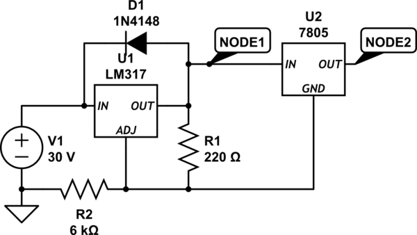
schematic

simulate this circuit – Schematic created using CircuitLab

\$\endgroup\$

3 Answers 3

2
\$\begingroup\$

Issues:

  1. The LM7805 ground should be to the voltage source ground
  2. 40V - 5V out = 35V you want to drop, at 750mA this is 26.3W, way too much for these regulators even with heatsinking.

If you want 5V, I recommend you use something like a R-78C5.0-1.0/X9, then using a normal LDO to get 3.3V from that assuming that both the 5V and 3.3V load use less than 1A.

\$\endgroup\$
2
  • \$\begingroup\$ Although I use them in many designs, I would caution that the R-78C type switching regulators are not always a drop-in solution. Their output ripple and ability to power capacitive loads or deal with start up inrush currents leave much to be desired. I have a board in front of me that uses a R-78C5.0-1.0 to power a MAX232 which fails to come up reliably unless the MAX232's outputs are disconnected at startup. \$\endgroup\$ Commented Apr 24, 2020 at 15:19
  • \$\begingroup\$ The datasheet tells you how much output capacitance the devices can handle. As long as you work within the limits of the device they are very hard to kill. I have used them with a similar regulator in an automotive enviroment with an rs232 tranciever. And after 3 years of operation the only thing that killed one was a bus being caught in a flood for a week. Though i was using an LDO to 3.3V to power the micro and rs232 \$\endgroup\$
    – Reroute
    Commented Apr 24, 2020 at 22:15
2
\$\begingroup\$

The function of LM317 is always maintain fixed V OUT-ADJ=Vref in order to design an internal negative feedback loop to raise the OUT voltage.

Vref is too low to drive 7805 and the xx_uA current is also just enough to drive the two series Resistors connected to ADJ and not any significant load.

\$\endgroup\$
0
\$\begingroup\$

It is not clear what your question is but there is something you can do to improve the design. I recommend adjusting R2 to lower the node 1 voltage below 24 V, because that is the limit on some 7805 datasheets.

For better reliability, adjust R32 such that the power dissipated in both regulators is equal at 750 mA output current. The current through each device is 0.75 A, the voltage is

((30 - 5) / 2) V

If the problem is that the node 1 voltage drops too much when the 7805 is connected, NOTE that the pinouts for the two regulators are significantly different.

And the equation is

P = E x I

\$\endgroup\$

Your Answer

By clicking “Post Your Answer”, you agree to our terms of service and acknowledge you have read our privacy policy.

Not the answer you're looking for? Browse other questions tagged or ask your own question.